


3-46
A
B
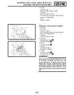
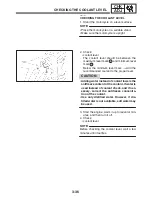
BLEEDING THE HYDRAULIC BRAKE SYSTEM
CHK
ADJ
WARNING
NOTE:
NOTE:
EAS00135
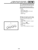
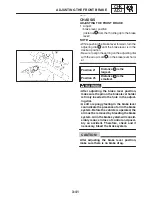
BLEEDING THE HYDRAULIC BRAKE
SYSTEM
Bleed the hydraulic brake system whenev-
er:
S
the system is disassembled.
S
a brake hose is loosened, disconnected or
replaced.
S
the brake fluid level is very low.
S
brake operation is faulty.
S
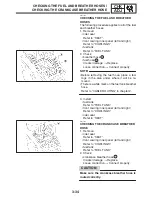
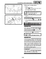
Be careful not to spill any brake fluid or allow
the brake fluid reservoir to overflow.
S
When bleeding the hydraulic brake system,
make sure there is always enough brake fluid
before applying the brake. Ignoring this pre-
caution could allow air to enter the hydraulic
brake system, considerably lengthening the
bleeding procedure.
S
If bleeding is difficult, it may be necessary to let
the brake fluid settle for a few hours. Repeat
the bleeding procedure when the tiny bubbles
in the hose have disappeared.
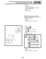
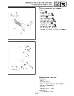
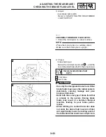
1. Bleed:
S
hydraulic brake system
a. Fill the brake fluid reservoir to the proper lev-
el with the recommended brake fluid.
b. Install the brake fluid reservoir diaphragm.
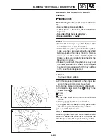
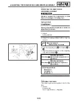
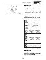
c. Connect a clear plastic hose
1
tightly to the
bleed screw
2
.
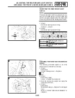
A Front
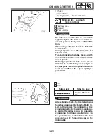
B Rear
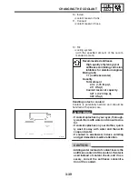
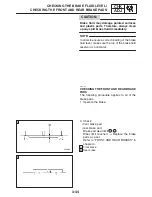
d. Place the other end of the hose into a con-
tainer.
e. Slowly apply the brake several times.
f. Fully pull the brake lever or fully press down
the brake pedal and hold it in position.
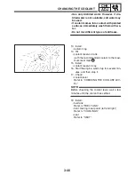
g. Loosen the bleed screw.
Loosening the bleed screw will release the pres-
sure and cause the brake lever to contact the
throttle grip or the brake pedal to fully extend.
Содержание FZ6-SS
Страница 1: ......
Страница 47: ...2 20 TIGHTENING TORQUES SPEC Cylinder head tightening sequence Crankcase tightening sequence...
Страница 52: ...2 25 COOLING SYSTEM DIAGRAMS SPEC 1 Radiator 2 Oil cooler COOLING SYSTEM DIAGRAMS...
Страница 53: ...2 26 COOLING SYSTEM DIAGRAMS SPEC 1 Water pump 2 Oil cooler 3 Radiator...
Страница 54: ...2 27 COOLING SYSTEM DIAGRAMS SPEC 1 Oil cooler 2 Water pump...
Страница 55: ...2 28 COOLING SYSTEM DIAGRAMS SPEC 1 Radiator 2 Thermostat...
Страница 56: ...2 29 ENGINE OIL LUBRICATION CHART SPEC ENGINE OIL LUBRICATION CHART...
Страница 57: ...2 30 LUBRICATION DIAGRAMS SPEC 1 Oil level switch 2 Oil cooler 3 Relief valve LUBRICATION DIAGRAMS...
Страница 58: ...2 31 LUBRICATION DIAGRAMS SPEC 1 Oil pump 2 Exhaust camshaft 3 Intake camshaft 4 Oil strainer...
Страница 59: ...2 32 LUBRICATION DIAGRAMS SPEC 1 Oil cooler 2 Oil strainer 3 Oil level switch 4 Oil pump...
Страница 60: ...2 33 LUBRICATION DIAGRAMS SPEC 1 Main axle 2 Oil pump 3 Relief valve...
Страница 61: ...2 34 LUBRICATION DIAGRAMS SPEC 1 Cylinder head 2 Intake camshaft 3 Exhaust camshaft 4 Crankshaft...
Страница 62: ...2 35 LUBRICATION DIAGRAMS SPEC 1 Main axle 2 Drive axle...
Страница 398: ...8 27 LIGHTING SYSTEM ELEC EAS00780 LIGHTING SYSTEM CIRCUIT DIAGRAM...
Страница 405: ...8 34 SIGNALING SYSTEM ELEC EAS00793 SIGNALING SYSTEM CIRCUIT DIAGRAM...
Страница 433: ...FZ6 SS FZ6 SSC WIRING DIAGRAM...
Страница 435: ......


