


4-53
FRONT FORK
CHAS
CAUTION:
NOTE:
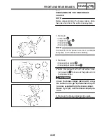
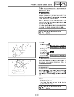
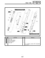
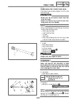
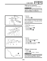
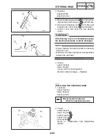
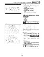
7. Install:
S
dust seal
1
(with the fork seal driver weight)
Fork seal driver weight
90890-01367
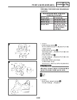
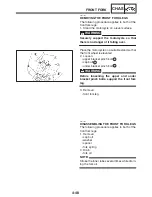
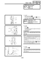
8. Fill:
S
front fork leg
(with the specified amount of the recom-
mended fork oil)
Quantity (each front fork leg)
0.467 L (0.41 Imp qt, 0.49 US qt)
Recommended oil
Suspension oil “01” or
equivalent
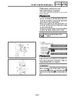
S
Be sure to use the recommended fork oil.
Other oils may have an adverse effect on
front fork performance.
S
When disassembling and assembling the
front fork leg, do not allow any foreign ma-
terial to enter the front fork.
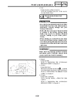
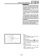
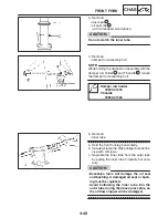
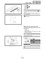
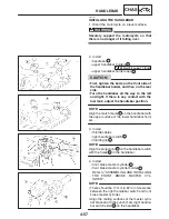
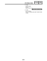
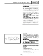
9. Measure:
S
front fork leg oil level
a
Out of specification
!
Correct.
Front fork leg oil level (from the
top of the inner tube, with the
inner tube fully compressed and
without the fork spring)
134 mm (5.28 in)
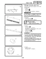
S
While filling the front fork leg, keep it upright.
S
After filling, slowly pump the front fork leg up
and down to distribute the fork oil.
Содержание FZ6-SS
Страница 1: ......
Страница 47: ...2 20 TIGHTENING TORQUES SPEC Cylinder head tightening sequence Crankcase tightening sequence...
Страница 52: ...2 25 COOLING SYSTEM DIAGRAMS SPEC 1 Radiator 2 Oil cooler COOLING SYSTEM DIAGRAMS...
Страница 53: ...2 26 COOLING SYSTEM DIAGRAMS SPEC 1 Water pump 2 Oil cooler 3 Radiator...
Страница 54: ...2 27 COOLING SYSTEM DIAGRAMS SPEC 1 Oil cooler 2 Water pump...
Страница 55: ...2 28 COOLING SYSTEM DIAGRAMS SPEC 1 Radiator 2 Thermostat...
Страница 56: ...2 29 ENGINE OIL LUBRICATION CHART SPEC ENGINE OIL LUBRICATION CHART...
Страница 57: ...2 30 LUBRICATION DIAGRAMS SPEC 1 Oil level switch 2 Oil cooler 3 Relief valve LUBRICATION DIAGRAMS...
Страница 58: ...2 31 LUBRICATION DIAGRAMS SPEC 1 Oil pump 2 Exhaust camshaft 3 Intake camshaft 4 Oil strainer...
Страница 59: ...2 32 LUBRICATION DIAGRAMS SPEC 1 Oil cooler 2 Oil strainer 3 Oil level switch 4 Oil pump...
Страница 60: ...2 33 LUBRICATION DIAGRAMS SPEC 1 Main axle 2 Oil pump 3 Relief valve...
Страница 61: ...2 34 LUBRICATION DIAGRAMS SPEC 1 Cylinder head 2 Intake camshaft 3 Exhaust camshaft 4 Crankshaft...
Страница 62: ...2 35 LUBRICATION DIAGRAMS SPEC 1 Main axle 2 Drive axle...
Страница 398: ...8 27 LIGHTING SYSTEM ELEC EAS00780 LIGHTING SYSTEM CIRCUIT DIAGRAM...
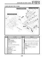
Страница 405: ...8 34 SIGNALING SYSTEM ELEC EAS00793 SIGNALING SYSTEM CIRCUIT DIAGRAM...
Страница 433: ...FZ6 SS FZ6 SSC WIRING DIAGRAM...
Страница 435: ......


