


8-50
FUEL PUMP SYSTEM
ELEC
YES
NO
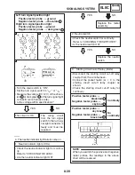
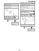
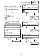
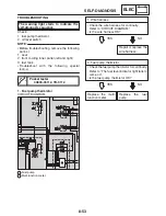
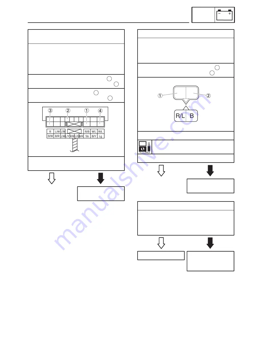
5 Starting circuit cut-off relay (fuel injection
system relay)
S
Disconnect the starting circuit cut-off relay
coupler from the wire harness.
S
Connect the pocket tester (
Ω
1) and bat-
tery (12V) to the starting circuit cut-off relay
coupler as shown.
Replace the starting
circuit cut-off relay.
Positive battery lead
!
red / black
Negative battery lead
!
blue / yellow
1
2
Positive tester probe
!
red
Negative tester probe
!
red / blue
3
4
S
Does the starting circuit cut-off relay have
continuity between red and red / blue?
YES
NO
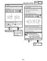
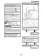
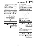
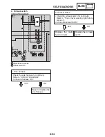
6. Fuel pump resistance
S
Disconnect the fuel pump coupler from the
wire harness.
S
Connect the pocket tester (
Ω
1) to the fuel
pump coupler as shown.
Properly connect or
repair the fuel sys-
tem’s wiring.
1
2
Positive tester probe
!
red / blue
Negative tester probe
!
black
EAS00817
YES
NO
Fuel pump resistance
0.2
X
3.0
Ω
at 20
_
C (68
_
F)
S
Is the fuel pump OK?
Replace the fuel
pump.
S
Measure the fuel pump resistance.
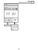
7. Wiring
S
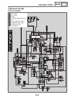
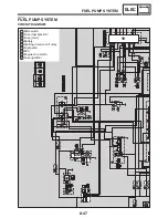
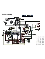
Check the entire fuel pump system’s wiring.
Refer to “CIRCUIT DIAGRAM”.
S
Is the fuel system’s wiring properly con-
nected and without defects?
EAS00818
Replace the ECU.
EAS00759
Содержание FZ6-SS
Страница 1: ......
Страница 47: ...2 20 TIGHTENING TORQUES SPEC Cylinder head tightening sequence Crankcase tightening sequence...
Страница 52: ...2 25 COOLING SYSTEM DIAGRAMS SPEC 1 Radiator 2 Oil cooler COOLING SYSTEM DIAGRAMS...
Страница 53: ...2 26 COOLING SYSTEM DIAGRAMS SPEC 1 Water pump 2 Oil cooler 3 Radiator...
Страница 54: ...2 27 COOLING SYSTEM DIAGRAMS SPEC 1 Oil cooler 2 Water pump...
Страница 55: ...2 28 COOLING SYSTEM DIAGRAMS SPEC 1 Radiator 2 Thermostat...
Страница 56: ...2 29 ENGINE OIL LUBRICATION CHART SPEC ENGINE OIL LUBRICATION CHART...
Страница 57: ...2 30 LUBRICATION DIAGRAMS SPEC 1 Oil level switch 2 Oil cooler 3 Relief valve LUBRICATION DIAGRAMS...
Страница 58: ...2 31 LUBRICATION DIAGRAMS SPEC 1 Oil pump 2 Exhaust camshaft 3 Intake camshaft 4 Oil strainer...
Страница 59: ...2 32 LUBRICATION DIAGRAMS SPEC 1 Oil cooler 2 Oil strainer 3 Oil level switch 4 Oil pump...
Страница 60: ...2 33 LUBRICATION DIAGRAMS SPEC 1 Main axle 2 Oil pump 3 Relief valve...
Страница 61: ...2 34 LUBRICATION DIAGRAMS SPEC 1 Cylinder head 2 Intake camshaft 3 Exhaust camshaft 4 Crankshaft...
Страница 62: ...2 35 LUBRICATION DIAGRAMS SPEC 1 Main axle 2 Drive axle...
Страница 398: ...8 27 LIGHTING SYSTEM ELEC EAS00780 LIGHTING SYSTEM CIRCUIT DIAGRAM...
Страница 405: ...8 34 SIGNALING SYSTEM ELEC EAS00793 SIGNALING SYSTEM CIRCUIT DIAGRAM...
Страница 433: ...FZ6 SS FZ6 SSC WIRING DIAGRAM...
Страница 435: ......


