
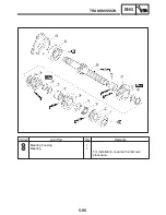


5-100
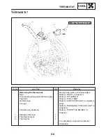
TRANSMISSION
ENG
NOTE:
NOTE:
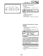
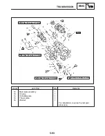
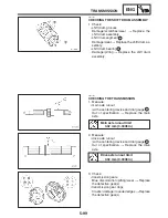
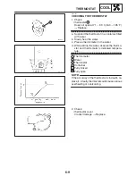
4. Check:
S
transmission gear engagement
(each pinion gear to its respective wheel
gear)
Incorrect
!
Reassemble the transmission
axle assemblies.
5. Check:
S
transmission gear movement
Rough movement
!
Replace the defective
part(s).
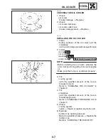
6. Check:
S
circlips
Bends / damage / looseness
!
Replace.
EAS00430
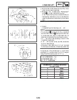
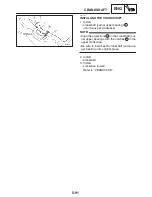
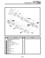
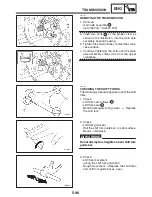
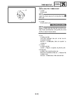
INSTALLING THE TRANSMISSION
1. Install:
S
oil pipe
1
S
main axle assembly
2
(with the Torx
wrench T30)
Make sure to caulk the bolts at three positions
after installing the bearing housing.
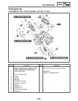
2. Install:
S
shift fork “C”
3
S
shift drum assembly
4
S
shift fork guide bar
S
The embossed marks on the shift forks should
face towards the right side of the engine and
be in the following sequence: “R”, “C”, “L”.
S
Carefully position the shift forks so that they
are installed correctly into the transmission
gears.
S
Install shift fork “C” into the groove in the 3rd
and 4th pinion gear on the main axle.
Содержание FZ6-SS
Страница 1: ......
Страница 47: ...2 20 TIGHTENING TORQUES SPEC Cylinder head tightening sequence Crankcase tightening sequence...
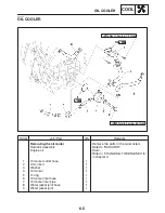
Страница 52: ...2 25 COOLING SYSTEM DIAGRAMS SPEC 1 Radiator 2 Oil cooler COOLING SYSTEM DIAGRAMS...
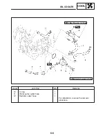
Страница 53: ...2 26 COOLING SYSTEM DIAGRAMS SPEC 1 Water pump 2 Oil cooler 3 Radiator...
Страница 54: ...2 27 COOLING SYSTEM DIAGRAMS SPEC 1 Oil cooler 2 Water pump...
Страница 55: ...2 28 COOLING SYSTEM DIAGRAMS SPEC 1 Radiator 2 Thermostat...
Страница 56: ...2 29 ENGINE OIL LUBRICATION CHART SPEC ENGINE OIL LUBRICATION CHART...
Страница 57: ...2 30 LUBRICATION DIAGRAMS SPEC 1 Oil level switch 2 Oil cooler 3 Relief valve LUBRICATION DIAGRAMS...
Страница 58: ...2 31 LUBRICATION DIAGRAMS SPEC 1 Oil pump 2 Exhaust camshaft 3 Intake camshaft 4 Oil strainer...
Страница 59: ...2 32 LUBRICATION DIAGRAMS SPEC 1 Oil cooler 2 Oil strainer 3 Oil level switch 4 Oil pump...
Страница 60: ...2 33 LUBRICATION DIAGRAMS SPEC 1 Main axle 2 Oil pump 3 Relief valve...
Страница 61: ...2 34 LUBRICATION DIAGRAMS SPEC 1 Cylinder head 2 Intake camshaft 3 Exhaust camshaft 4 Crankshaft...
Страница 62: ...2 35 LUBRICATION DIAGRAMS SPEC 1 Main axle 2 Drive axle...
Страница 398: ...8 27 LIGHTING SYSTEM ELEC EAS00780 LIGHTING SYSTEM CIRCUIT DIAGRAM...
Страница 405: ...8 34 SIGNALING SYSTEM ELEC EAS00793 SIGNALING SYSTEM CIRCUIT DIAGRAM...
Страница 433: ...FZ6 SS FZ6 SSC WIRING DIAGRAM...
Страница 435: ......


