Installation
Turb PLUS 2000
100193 Rev 0 ba77254e01 11/2020
13
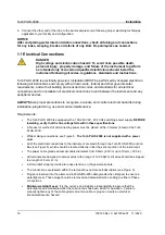
1. Using masking tape, affix the mounting template to the vertical surface of the selected mounting
location and mark location for screws.
•
The Turb PLUS 2000 is designed for
vertical wall mounting
. If wall mounting is not practical, the
instrument can be mounted on any suitable vertical, flat surface.
•
Make sure that the mounting position is level.
2. The overall mounting dimensions of the Turb PLUS 2000 are shown in Figure 3, below. Measure to
confirm that the mounting location has sufficient space and that there is at least 20 cm (8 in) free area
above the instrument when mounted. This will ensure enough room for calibration and cuvette
maintenance.
3. Carefully remove the mounting template from the wall, keeping it in one piece for future reference and
use.
4. Install wall anchors (if needed) - Following manufacturer’s instructions for the wall anchors, and using
the mounting template as a guide, insert wall anchors for each mounting position.
5.
Mount the Junction Box First
. The Turb PLUS 2000 is designed to have the Junction Box cradled
under the upper portion of the instrument containing the keypad and display.
a. Position the Junction Box of the Turb PLUS 2000 to match the 2 lower wall
anchors.
b. Mount the Junction Box first by inserting the M4 (#8) screws through the 2
inside the Junction Box. Use wall anchors as needed.
c. Using the screwdriver, hand-tighten both screws, ensuring that the Junction
Box is firmly and securely attached.
6.
Mount the upper keypad and display section.
After securely mounting the junction box, mount the
upper portion of the Turb PLUS 2000 so that the junction box is cradled under the upper portion.
a. Position the upper portion of the Turb PLUS 2000 to match the remaining
holes or wall anchors.
b. Insert M6 (1/4”) screws through the 4 tabs on the upper portion of the Turb
PLUS 2000 and into the wall anchors.
c. Using the screwdriver or driver gun, to tighten the screws, ensuring that the
upper portion is firmly and securely attached.
7. Confirm that Turb PLUS 2000 is securely mounted to the wall (or vertical surface) and positioned:
•
Within 2-3 meters (6 to10 ft) of the sampling point to ensure a quick response time.
•
Isolated from vibration, and not susceptible to freezing or temperature extremes.
•
Suitable vertical and flat surface that can support the product’s weight 5 kg (10lbs).
•
20 cm (8 in) free area above the instrument, allowing room for calibration and cuvette maintenance.
•
The front display should be positioned at eye level or a suitable level to read and reach controls -
approximately 1.4 Meters (4.5 feet) to 2 meters (6.5 feet) from the floor.
•
Confirm that the unit is level.
Содержание 600026
Страница 1: ...OPERATING MANUAL 100193 Rev 0 ba77254e01 11 2020 Turb PLUS 2000 PROCESS TURBIDIMETER...
Страница 2: ...Turb PLUS 2000 2 100193 Rev 0 ba77254e01 11 2020 Copyright 2020 Xylem Analytics Germany GmbH...
Страница 58: ......
Страница 59: ......


