background image

x-Lab Dot Matrix Printer XDP-321 User's Manual 

- 6 - 


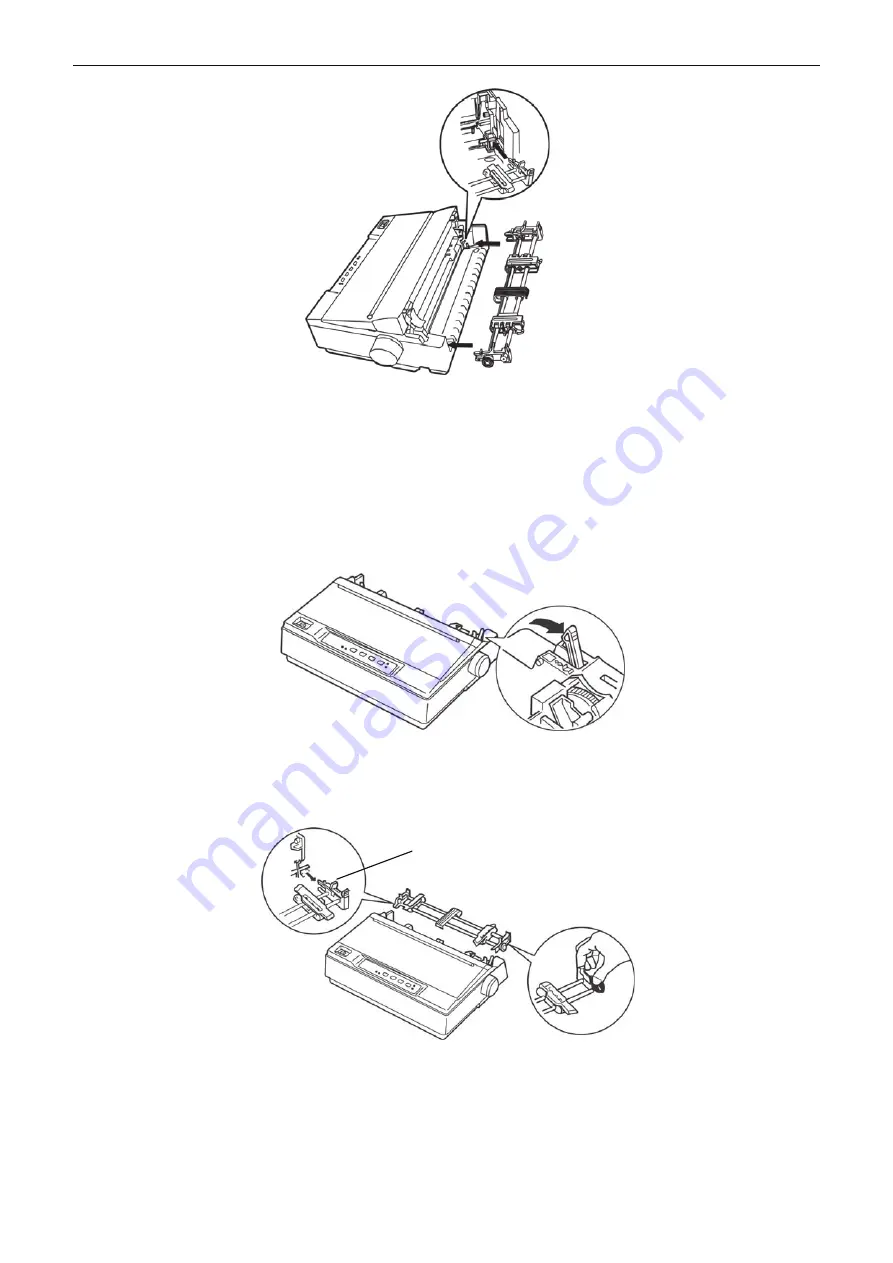
1.6.2 Installing the Draught Tractor 

If the tractor has been installed in the push position (rear side of printer), take out the tractor, remove 

the tear-off position, and install the tractor in the pull position. The concrete steps are as follows. 

1. Make sure the printer is turned off, take out the paper guide, and then pull the paper select lever to 

the tractor paper position according to the following figure. 


2. Take out the drive tractor as the following steps: Press the lock sheets of the tractor tightly (As shown 

in Figure 1-15), and pull out the tractor from the printer, and then remove the window. 


3. Press the lock sheet of the tear-off position tightly (shown as Figure 1-16), and then lift it upwards. 


Lock sheet 

Figure 1.6.1 Install the drive tractor

Figure 1.6.2-1 Set paper select lever

Figure 1.6.2-2 Take out the drive tractor

Содержание XDP-321

Страница 1: ......

Страница 2: ...ut Trademark is a registered trademark of xLab Global LLC in United States of America All other trademarks are the property of their respective owners and used for identification purpose only All the Product information are subject to change without prior notice ...

Страница 3: ...attention to the following promises when using this manual Warning Warnings must be followed carefully to avoid bodily injury Caution Cautions must be observed to avoid damage to your equipment Note Notes contain important information and useful tips on the operation of your printer ...

Страница 4: ...tion To ensure reliable operation of the product and to protect it from overheating do not block or cover this area 8 This product should never be placed near or over a radiator or heat origin and should avoid from direct sunshine 9 Do not use in locations subject to high humidity or dust levels Excessive humidity and dust may cause equipment damage or fire 10 Don t remove the printer s out cover ...

Страница 5: ...the control panel pull the paper select lever to the cut sheet position and then load the cut sheet to print If you want to use tractor paper again pull the paper select lever to the tractor paper position then press LOAD EJECT button tractor paper may be fed to the printer and print Eject Function The function allows the user to eject the cut sheet or tractor paper through the facility key on the...

Страница 6: ...1 9 1 Connecting to the Parallel Interface Cable 10 1 9 2 Connecting to the USB Interface Cable 10 1 9 3 Connecting to the Serial Interface Cable 10 1 10 Installing Driver 11 1 10 1 Auto installing way Recommended 11 1 10 2 Hand operated installing way 11 Chapter 2 Control Panel 14 2 1 LED Indicator 14 2 2 Key Functions 14 2 2 1 In the Tractor Paper Mode 14 2 2 2 In the Cut Sheet Mode 15 2 2 3 Pri...

Страница 7: ... 35 Chapter 5 Printer Maintenance and Technical Service 36 5 1 Cleaning the Printer 36 5 2 Contact the Technical Service Centre 36 Appendix A Specifications 37 A 1 General 37 A 2 Interface Specifications 39 A 2 1 Parallel Interface 39 A 2 2 USB Interface 39 A 2 3 Serial Interface 39 Chapter B Paper Specification 41 B 1 Paper Specification and Printable Area 41 B 1 1 The Notice Related to Paper 41 ...

Страница 8: ...er open the window of the printer and remove the protective materials as shown in Figure 1 2 2 Save all the original packing materials so that they can be used when transporting the printer 1 3 Main Parts of the Printer Figure1 3 Figure1 4 and Figure 1 5 show the main parts of XDP 321 Protective materials Figure 1 2 Remove the protective materials Figure 1 1 Packing list Protective materials Print...

Страница 9: ...printer cable to reach 3 Moderate environmental conditions Select a cool dry area and protect your printer from direct sunlight excessive heat moisture or dust Paper feed knob Power switch Ribbon cartridge Print head Paper guide Paper select lever Control panel Gap adjust lever Tear off position Figure 1 3 Main parts of printer Front view Figure1 4 Main parts of printer Side view Power supply inle...

Страница 10: ...per feeding secure them to a leg of the stand if possible 1 5 Installing the Printer Follow the steps in this section to install your printer 1 5 1 Installing the Paper Feed Knob 1 Insert the paper feed knob into the hole on the right side of the printer As shown below 2 Press firmly on the knob until it fits against the printer case 1 5 2 Installing the Ribbon Cartridge 1 Before installing the ri...

Страница 11: ... from the ribbon so that it is easier to install 7 Insert the ribbon cartridge into the printer as the following figure shown then hold both sides of the cartridge aim the buckles at the mounting slots on both sides of the printer press them down until they locked into place Lock sheet Tear off position Figure 1 5 2 3 Remove the tear off position Figure 1 5 2 5 Slide the print head to the middle o...

Страница 12: ...n the printer tear paper normally If the print position requires high precision such as printing on the paper with forms you are suggested using draught tractor 1 6 1 Installing the Drive Tractor Aim the mounting slots on both sides of tractor at the alignment pins which are at the rear of printer press forward till it locks in place Shown as Figure 1 13 Metal guide slice Print head Figure 1 5 2 7...

Страница 13: ... the paper guide and then pull the paper select lever to the tractor paper position according to the following figure 2 Take out the drive tractor as the following steps Press the lock sheets of the tractor tightly As shown in Figure 1 15 and pull out the tractor from the printer and then remove the window 3 Press the lock sheet of the tear off position tightly shown as Figure 1 16 and then lift i...

Страница 14: ...required by the printer matches that of your electrical outlet 3 Plug one end of power cord into the printer power supply inlet 4 Plug the other end of power cord into a properly grounded electrical outlet Lock sheet Tear off position Figure 1 6 2 3 Take out the tear off position Figure 1 6 2 4 Install the draught tractor Figure 1 7 1 Turn off the printer Power switch Electrical outlet Power cord ...

Страница 15: ...e POWER LED blinks and the ONLINE LED is off which indicates the printer is out of paper 3 Slide the left guide track until it reaches at the triangular guide mark Then adjust the right guide track to match the width of your paper 4 Slide a sheet of paper down between the two guide tracks until it meets resistance The printer loads the sheet automatically and begins printing when pressing the ONLI...

Страница 16: ...wn below ASCII Self test mode x Lab XDP 321 VX X 20XX XX XX 0123456789 ABCDEFGHIJKLMNOPQRSTUVWXYZ _ ab 0123456789 ABCDEFGHIJKLMNOPQRSTUVWXYZ _ abcd 0123456789 ABCDEFGHIJKLMNOPQRSTUVWXYZ _ abcde e Serial interface USB interface Parallel interface Figure 1 8 4 Load cut sheet Figure 1 8 6 ASCII self test mode Figure 1 9 Lay the rear side of printer upwards Warning The window must be closed while prin...

Страница 17: ...nd of the USB interface cable flat shape into the computer s USB interface 2 Plug the B end of the USB interface cable square shape into the printer s USB interface As Figure1 26 shown 1 9 3 Connecting to the Serial Interface Cable 1 Turn off both the computer and the printer Plug one end of the serial interface cable into the printer s serial interface Tighten the screws on both sides and make th...

Страница 18: ...rding to the operating system environment you should select the path as follow CD ROM Drivers WIN2000 XP Vista Win7 click Open then click OK to return to the window of Install Printer Software click Next 6 Follow the guide and click Next gradually till the installation is finished 2 The hand operated installing steps of USB interface cable The following steps are used Windows XP as an example Ther...

Страница 19: ... path as follow CD ROM Driver WIN98 WINME then click OK 4 A window of Install From Disk pops up click OK return to a window of Add Printer select the respective model and then click Next 5 A window of Printer port pops up select Available ports such as select LPT1 Printer Port click Next and then show the printer s name If the system is not installed by other printer driver process the printer is ...

Страница 20: ...k please click Browse select the path as follow CD ROM Driver WIN98 WINME and then click OK 4 A window of Install From Disk pops up click OK return to a window of Add Printer then click Next 5 A window of Printer port pops up select Available ports select JMUSB click Next and then show the printer s name If the system is not installed by other printer driver process the printer is treated as defau...

Страница 21: ... EJECT 1 When the paper is at the ready position press LOAD EJECT button the paper will be fed to the printing home position automatically 2 When the paper is at the print position press LOAD EJECT button in the offline mode printer will eject one page when the eject able length is longer than one page If the paper eject able length is less than one page the paper will go back to the ready positio...

Страница 22: ...eed 3 Press the ONLINE button to save the value and exit the mode 2 2 4 Micro Adjust of Printing Home Position and Tear off Position 1 After turning on the printer install tractor paper properly using drive tractor and feed paper to the printing home position or tear off position 2 Hold the ONLINE button down for over 3 seconds in the offline mode till the ONLINE LED blinks with a beep 3 Press or ...

Страница 23: ...n test mode TEAR POWER English self test mode TEAR LF FF POWER Hex dump mode 2 3 Paper Select Lever Use the paper select lever to specify the printing mode of cut sheet or tractor paper If you use cut sheet to print please pull the paper select lever to the cut sheet position if you use tractor paper to print pull the paper select lever to the tractor paper position 2 4 Paper Feed Knob The paper f...

Страница 24: ...se the table below to select the appropriate paper thickness Copies including original Lever position 1 d e v r e s e R Standard paper cut sheet or tractor paper 0 2 ply 1 3 ply 2 Multi ply paper 4 ply 3 20 pound 4 Envelopes 24 pound 5 6 d e v r e s e R ...

Страница 25: ...opes Please make sure the printing contents are all within the printable area while printing The correlative printable area please refer to Appendix A 3 1 1 Loading Cut Sheet 1 Make sure the printer is powered off and open the window of the printer refers to Gap adjust lever of this manual according to the paper type 2 Close the window and set paper select lever to the cut sheet position 3 Raise t...

Страница 26: ...ar off Position if necessary 3 1 2 Loading Tractor Paper If you use the tractor paper you must decide which tractor to be installed Then you install the tractor in the corresponding way For convenience to switch between printing on cut sheet and tractor paper or for convenience to tear off the tractor paper you should use the tractor in push position The printer leaves the factory with the tractor...

Страница 27: ...in the tractor paper position Open the printer window and then adjust the gap adjust lever according to paper type 2 Make sure the tractor is installed correctly refer to chapter 1 3 Pull the sprocket lock lever of the drive tractor upwards to release the sprocket As shown below 4 Slide the left sprocket referring to the scale on the printer The printer prints to the right of the scale 0 Push the ...

Страница 28: ...de to make them stop at the triangular mark on the paper guide As shown below 8 Make sure the window is closed Turn on the printer and Press LOAD EJECT button to feed paper You can adjust the printing home position according to Micro Adjust of Printing Home Position and Tear off Position if necessary When the printer receives command it begins printing automatically Figure 3 1 2 1 5 Load the tract...

Страница 29: ...r according to the paper type 2 Make sure the tractor is installed correctly refer to chapter 1 3 Pull the sprocket lock lever of the drive tractor upwards to release the sprocket As shown below 4 Insert the paper into the paper slot as shown below printing side is faced down then pull it out from the position between the print head and the platen Adjust horizontal position of the paper using the ...

Страница 30: ...ket to remove any slack from the paper and lock it in place 7 To separate the paper from loading and ejecting it is necessary to install the paper guide Hold it horizontally and aim it at the printer s mounting slots Then slide the paper guide toward the rear side of the printer until it locks in place 8 Slide the left and right guide tracks to the center until it stops at the triangular mark on t...

Страница 31: ...r Pull straight the paper upwards and then adjust the left and right sprockets until they match the width of the paper Then fit the tractor holes of the paper into the sprockets of the draught tractor lock the sprockets at last The paper should not be twisted 6 If the tractor holes of the paper do not match the sprocket of the draught tractor when tightening the paper lengthways then you can do as...

Страница 32: ...ns 4 Do not leave labels in the printer while doing other jobs or they would stick on the platen and cause paper jam when it resumes printing 5 Remove the labels from the printer firstly tear off the fresh supply at the rear of the printer and then press LF FF button to eject the remaining labels from the printer 3 1 5 Loading Envelopes The method of loading envelopes is generally the same with th...

Страница 33: ...eturns to the home position with the printer beeping once The ONLINE LED is off and the Power LED blinks which denotes that paper out occurs 2 Set the paper select lever to the proper position If in cut sheet mode the paper select lever should be in the cut sheet position otherwise it should be in the tractor paper position 3 After loading paper in cut sheet mode the printer would print out the cu...

Страница 34: ... INCH R E T T E L H C N I 5 8 H C N I 7 A4 12 INCH FORM LOCK OFF ON PAGE SKIP OFF ON COMPRESS PRINT NORMAL 75 50 PRINT SETUP PRINT DIR BI DIR UNI DIR AUTO PRT SPEED NOR SPEED HI SPEED SUP SPEED AUTO LF OFF ON TEAR OFF OFF ON TEAR POS TEARER HEAD TOP PIN SWITCH OFF ON IMPACT MODE NORMAL COPY 1 COPY 2 SERIAL 1 F BAUD RATE 19200 BPS 9600 BPS 4800 BPS 2400 BPS 1200 BPS PARITY NONE ODD EVEN DATA BIT 8 ...

Страница 35: ...he function of online aptitude parameter settings which can be set in the PC with the driver installed in The concrete setting steps are shown as follows 1 Make sure that the host and the printer are connected with a cable and both the host and the printer are turned on the printer should be in normal working condition as well 2 Under the operating system of WIN 2000 WIN XP VISTA WIN 7 click Start...

Страница 36: ...er s instruction will be sent to the printer 8 The printer s parameter settings will be changed at once after receiving the instruction and it is not necessary to restart the printer 9 After finishing settings click OK exit the Properties window 3 3 Printer Setting Descriptions This section describes all the settings available in the Menu Setup Mode n o i t p i r c s e D s n o i t p O EMULATION Sp...

Страница 37: ...e priority to print data instruction COMPRESS PRINT After selecting this function on printer would print out transverse compressed content according to the specified percentage in normal speed When auto compress mode is selected printer would detect paper width automatically and choose the proper percentage to print PRINT DIR Select the printing direction of the print head unidirectional bidirecti...

Страница 38: ...e control panel at the same time while turning on the printer The POWER and ONLINE LED indicators on the control panel blink 3 times simultaneously with two beeps to confirm that printer s factory settings have been restored 2 Release the buttons and switch the printer off and on again 3 After these steps the printer s factory settings work ...

Страница 39: ...olled by an outside switch or automatic timer use another outlet 3 Plug another electrical device such as a lamp into the outlet to determine whether the outlet operates properly Phenomenon 2 The LEDs blink temporarily and then go off The LEDs stay off even when the power is turned on again Solutions Check whether the printer s rating voltage matches with the power cord If not unplug the power cor...

Страница 40: ...acters have parts missing at the top or bottom Solutions The ribbon cartridge may not be installed properly See chapter Installing the Ribbon Cartridge Phenomenon 2 The printout is faint Solutions The ribbon may be worn out Replace the ribbon as described on chapter Installing the Ribbon Cartridge The ribbon can not move smoothly Solutions The ribbon may be worn out Replace the ribbon as described...

Страница 41: ...Phenomenon 2 Paper feeding is crooked or paper jam occurs Solutions Turn off the printer and remove the jammed paper Reinsert a piece of cut sheet straightly into the paper guide and adjust the paper guide to match with paper width Make sure that the window is closed and power on again Phenomenon 3 Paper does not eject completely Solutions 1 Use the LOAD EJECT button to eject the paper 2 Make sure...

Страница 42: ...ode Enter the alignment adjust mode to improve the print quality when the printer has been used for a long time 1 Turn on the printer load paper and then turn off the printer 2 Entering method of alignment adjust mode In the online mode press and hold on the LF FF key and TEAR key until the Power and ONLINE indicators blink simultaneously the printer enters LQ and DP alignment adjust mode DP align...

Страница 43: ...make lube scattered Cleaning the paper feed path Wipe off wasted paper clean dirt and dust 5 2 Contact the Technical Service Centre If malfunction occurs and can not be solved through the operation shown in 4 2 the components of the printer are damaged during using or you need to buy some consumables please contact the nearest technical service centre Figure 5 1 Cleaning the printer Carriage shaft...

Страница 44: ...erleaved 2 of 5 Matrix 2 of 5 Industrial 2 of 5 Code 39 Code 128 B Code 128 C NW 7 Character pitch ASCII 10 CPI 12 CPI 15 CPI 17 1 CPI proportional Line spacing 1 6 inch programmable in 1 432 inch increments 3 inches per second Continuous feed Normal mode 63 ms advance one line 1 6 inch 3 inches per second Continuous feed Paper feed Speed Copy mode 63 ms advance one line 1 6 inch Interface This pr...

Страница 45: ...ement Automatic Emulation Match Online Parameter Setting Physical dimensions 366 Width 275 Depth 156 Height mm Weight Approx 4 3 Kg Temperature 5 35 Operating environment Humidity 25 80 RH No condensation Temperature 40 55 Environmental conditions Storage environment Humidity 93 40 No condensation Rated voltage 220V AC Power requirements Rated frequency range 50Hz Power consumption Operating 47 W ...

Страница 46: ... 2 2 USB Interface The following table provides the standardized contact terminating assignments by number and color for Series A and Series B connectors of Full speed USB 2 0 A 2 3 Serial Interface The serial interface has the following characteristics Baudrate bps 1200 bps 2400 bps 4800 bps 9600 bps 19200 bps selectable Data length 7 or 8 bit selectable Start bit 1 bit Parity bit Odd even or non...

Страница 47: ...cription 1 Protective Ground FG Printer s chassis ground 2 Transmitted Data TXD SD Out Printer has transmitted serial data 3 Received Data RXD RD In Printer has received serial data 7 Signal Ground SG Return path for data control signals 20 Data Terminal Ready DTR Out Positive when the printer is ready to receive data and negative when the printer is not ready Figure A 2 3 Serial interface connect...

Страница 48: ...ion Paper being cut out or has hole Paper with metal such as pins clips and staples Paper with paste outside or which is uneven or flake off Rough paper Tractor paper has crease besides the cross perforation Paper corner breaks or is creased Postcard or envelope is stuck with stamp or seal Break Flake off Tear Crease Tear Clip Staple Pin Note 1 The storage of the paper should be in the temperature...

Страница 49: ... the standard of 40 g m2 Single ply paper 52 90 g m 2 Weight Multi ply paper each sheet 40 64 g m 2 Single ply paper 0 39 mm Note 1 Total thickness Multi ply paper 0 26 mm Note 2 Caution Guarantee here means the specifications which accord with print specification noise specification and paper feed performance etc The meanings of symbol in Guarantee grade column are shown as follows Guarantee Can ...

Страница 50: ...luded in print specification Printable area Print area Note 1 This thickness is added by multi single ply papers and it is only achieved when just printing on the upper paper No need to copy 2 Refer to the requirement of the multi ply paper NCR paper the mount paper can be thicker than other plies but we can t guarantee the printing effect as it is influenced by paper difference Caution 1 Paper le...

Страница 51: ... a c i f i c e p S e m a N k r a M value W Paper width 148 257 mm L Paper length 90 mm Caution 1 A Home position 2 mm A Top printing unguaranteed area 8 mm B Bottom printing unguaranteed area 9 mm C Left printing unguaranteed area 3 mm D Right printing unguaranteed area 3 mm Printable area Unit mm Print area is not included in print specification Printable area Print area Print side Datum line Dat...

Страница 52: ... According to different storage conditions paper would easily become fold bend or curliness through manually disposal transport and deposit Therefore they would affect paper feeding when using these papers Thus please use them after amending according to the following regulations The papers which failed to come up to specifications would affect paper feeding seriously please do not use them Fold c...

Страница 53: ...equirement of tractor paper Single ply paper White paper Paper r e p a p R C N r e p a p y l p i t l u M Width 101 6 254 mm Length 145 mm Copy capability Max 4 copies Original 3 copies paper weight based on the standard of 40g m2 Single ply paper 52 82 g m 2 Weight Multi ply paper each sheet 40 64 g m 2 Single ply paper 0 39 mm Note 1 Total thickness Multi ply paper 0 26 mm Note 2 Paper with the w...

Страница 54: ...ny two gear holes center which is in the distance of 254mm in either side of the paper Printable Area Max 203 2 mm 13 mm 8 mm 13 mm Note 1 This thickness is added by multi single ply papers and it is only achieved when just printing on the upper paper No need to copy 2 Refer to the requirement of the multi ply paper NCR paper the mount paper can be thicker than other plies but we can t guarantee t...

Страница 55: ...holes center B 12 70 0 05 Distance between nearby gear holes center in the same side Accumulative error of distance between gear holes center Below 0 3 The accumulative error along the central line of any two gear holes which are 254mm apart Warp of gear hole center C Below 0 1 The maximal warp of the gear holes center in the same side Central warp of right and left gear holes E Below 0 15 The war...

Страница 56: ...ch is fixed through metal staple Point Pulp Point pulp should be in both ends it is not allow pointing pulp only in one end The point pulp position should be the same and the size is Φ3 Φ5mm The position of point pulp should be pressed down tightly to avoid warping There should not be any obvious crease on the point pulp position Each page of the point pulp paper is interleaving Interleaving betwe...

Страница 57: ...to avoid warping Line pulp 1 2 mm First page Third page Second page Forth page Fifth page 6 35 Loading direction Unit mm 6 35 Fixed tightly Not fixed tightly 25 4 Transverse perforation Above 2 Paper binding space is over 50 8mm 2inches 3 4 About 1 Press down to avoid warping If bind the four places together 50 8 Space The size and position of paper binding single Expanding figure of the binding p...

Страница 58: ...se unstable paper feed or paper jam etc Especially when the multi ply paper is with many pages it will deeply affect the stability of paper feed Please ensure the protuberance height is less than 1 mm Warp between toothed holes of each ply Please use the paper which toothed holes warp between each ply causes by the warp of multi ply papers superposition is less than 0 4 mm 6 35 Loading direction U...

Страница 59: ...and upturning in the top and bottom Or it may cause cheap printing quality or paper jam Especially for the new paper if it creases from the first few pages please do not use it Paper folding part Please fold the paper based on the transverse perforation It will affect paper feeding while the folding part sticks up as the following figure shown please do not use it Toothed holes section Warp is les...

Страница 60: ...Note 1 Sample 1 Envelope C4 324 229 No C6 162 114 Yes Note 2 DL 220 110 Yes C5 229 162 Yes Sample 2 Envelope C4 324 229 No Material Envelope which is Grade B or above Weight 80 120 g m 2 Top 6 25 mm Bottom 6 25 mm Left 6 25 mm Right 12 mm Note 3 Non guarantee Area From pulp position 5 mm Protrusive part Note 1 Envelope should not have solid edge the folding part in both sides and the bottom 2 Samp...

Страница 61: ...x Lab Dot Matrix Printer XDP 321 User s Manual 54 Sample 1 Envelope Front view Stamp Sample 1 Envelope Rear view 10 15 B6 DL ZL Envelope 15 20 C5 C4 Envelope ...

Страница 62: ...er XDP 321 User s Manual 55 Sample 1 Envelope print direction and printable area Stamp Sample 2 Envelope Front view Stamp Note To load envelope please place it on the paper guide with the front downwards and the rear upwards ...

Страница 63: ...x Lab Dot Matrix Printer XDP 321 User s Manual 56 Sample 2 Envelope Rear view ...

Страница 64: ... Dot Matrix Printer XDP 321 User s Manual 57 Sample 2 Envelope print direction and printable area Stamp Note To load envelope please place it on the paper guide with the front downwards and the rear upwards ...

Страница 65: ...commend using the recycled paper The specification of recycled paper should satisfy the using standard requirement Note 1 Label is not included in the guarantee list please don t use it 2 Problem occurs when using labels we will not guarantee the device and performance Caution Envelope refers to single layer envelope The double layer envelope is not supported and the envelope should not be with so...

Страница 66: ...ontal print position 16 ESC Set Relative Horizontal print position 17 ESC U Define Unit 18 ESC V Set Absolute Vertical Print Position 19 ESC v Set Relative Vertical Print Position 20 ESC J n 180 Line Feed 21 ESC j n 180 Reverse Line Feed 22 HT Horizontal Tab Printer control commands 23 VT Vertical Tab 24 ESC m n Reassign Graphics Mode 25 ESC Set Graphics Mode 26 ESC G Select Graphics Mode 27 ESC P...

Страница 67: ...lect demisemi size mode for Chinese character 50 FS Select Chinese character print mode 51 FS v Select Cancel form connect line 52 FS k Select Chinese font 53 FS Y Select Chinese character dot matrix and width 54 FS c Set Chinese character HMI Horizontal motion space 55 FS b Set Chinese character datum line Chinese character print command 56 ESC I Select Chinese CC DOS print mode 57 ESC k Select F...

Страница 68: ...haracters 89 ESC S n Select Superscript Subscript Mode Font enhancement 90 ESC T Cancel Superscript Subscript Mode 91 ESC C Set Form Length in Lines 92 ESC C NUL Set Form Length in Inches 93 ESC C Set Form Length in Defined Unit 94 ESC c Define Form Format 95 ESC N n Select Page Skip 96 ESC O Cancel Page Skip 97 ESC l Set Left Margin 98 ESC Q Set right Margin 99 ESC D Set Horizontal Tab Positions ...

Страница 69: ...Customer Support Warranty Registration from Texas USA MADE IN CHINA Product of ...

Отзывы: