03/02
Level 2 Troubleshooting
WorkCentre Pro 423/428
2-131
CHAPTER 2 TROUBLESHOOTING
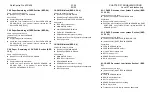
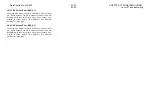
2.3.5 Other Problem FIP
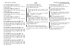
WARNING
Switch off the machine and disconnect the power
cord from the customer’s outlet while performing
tasks that do not need electricity. Electricity can
cause death or injury.
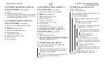
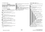
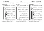
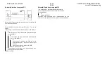
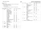
AC POWER FIP (BSD 1.1 1.2)
WARNING
Switch off the machine and disconnect the power
cord.
Perform the Power Outlet Check. Is the voltage correct?
Y
N
Check the circuit breaker at the customer.
Check the power cord for an open wire. The power cord is
normal.
Y
N
Replace the power cord.(PL7.1)
Connect the power cord to the outlet and the machine. Is the
voltage 100 VAC between the CIRCUIT BREAKER FS243(+)
and FS244(-)?
Y
N
Replace the CIRCUIT BREAKER. (PL7.1)
POWER UNIT FS11(+)FS12(-) Is the voltage 100 VAC ?
Y
N
Check between the CIRCUIT BREAKER and POWER
UNIT for an open wire or poor contact.
Is a CHOKE COIL or cheat connector installed to the POWER
UNIT P5? (100V model)
Y
N
Install a CHOKE COIL or cheat connector.
Is the voltage 100 VAC between the POWER UNIT J8-3(+) and
J8-6(-)?
Y
N
Replace the POWER UNIT. (PL7.1)
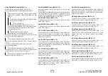
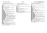
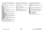
Turn on the MAIN POWER SW. Is the voltage 100 VAC
between the POWER UNIT J8-4(+) and J8-1(-)?
Y
N
A
B
A
B
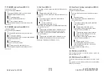
Is the voltage 100 VAC between the MAIN POWER SW
J620-4(+) and J620-1(-)?
Y
N
Is the voltage 100 VAC between the MAIN POWER
SW J620-6(+) and J620-3(-)?
Y
N
Check between the MAIN POWER SW and
POWER UNIT for an open wire or poor contact.
Replace the MAIN POWER SW. (PL2.3)
Check between the MAIN POWER SW and POWER UNIT
for an open wire or poor contact.
Replace the POWER UNIT. (PL7.1)
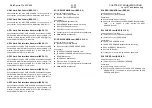
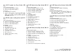
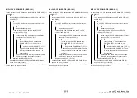
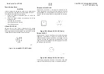
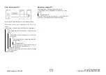
+24VDC POWER FIP (BSD 1.1 1.6)
Is the v24 VDC between the MCU/SW PWB J400-1(+)
and GND(-)?
Y
N
Is +24DC WIRE normal (no short circuit with theFRAME)?
Y
N
Repair the short circuit.
Is the v24 VDC between the POWER UNIT
J521-1(+) and GND(-)?
Y
N
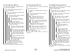
Is the v5 VDC between the POWER UNIT
J523-1(+) and GND(-)?
Y
N
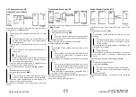
Is the v5 VDC between the MCU/SW
PWB J403-4(+) and GND(-)?
Y
N
Is the v5 VDC between the
MCU/PWB J400-10(+) and GND(-)?
Y
N
Is the v5 VDC between the
Power Unit J521-5(+) and GND(-)?
Y
N
Is the voltage 100 VAC between
the POWER UNIT J8-4(+) and
J8-1(-)?
Y
N
Perform AC POWER FIP.
P5VDC POWER FIP.
Check between the POWER UNIT
J521-5 and MCU/PWB J400-10 for
an open wire or poor contact.
Replace the POWER UNIT. (PL7.1)
Check between the POWER UNIT J523-1 and
MCU/SW PWB J403-4 for an open wire or
poor contact.
Replace the POWER UNIT. (PL7.1)
Check between the POWER UNIT and MCU/SW PWB for
an open wire or poor contact.
Check between the MCU/SW PWB and the corresponding part
for an open wire or poor contact.
Содержание WorkCentre Pro 423
Страница 1: ...Transmittal Page 3URGXFW RUN HQWUH 3UR 7LWOH 6HUYLFH 0DQXDO 3DUW 1XPEHU 3 6WDWXV QWLDO VVXH DWH 0DUFK...
Страница 2: ......
Страница 3: ...WorkCentre Pro 423 428 6HUYLFH 0DQXDO...
Страница 6: ......
Страница 8: ......
Страница 9: ...INTRODUCTION...
Страница 10: ......
Страница 24: ...WorkCentre 423 428 03 02 INTRODUCTION 14 7 Translation of Warnings...
Страница 25: ...CHAPTER 1 SERVICE CALL PROCEDURE...
Страница 26: ......
Страница 28: ...WorkCentre Pro 423 428 1 2 CHAPTER 1 SERVICE CALL PROCEDURE 03 02 1 1 Trimming...
Страница 31: ...CHAPTER 2 TROUBLESHOOTING...
Страница 32: ......
Страница 76: ...WorkCentre Pro 423 428 2 44 CHAPTER 2 TROUBLESHOOTING 03 02 2 3 Level 2 Troubleshooting...
Страница 242: ...WorkCentre Pro 423 428 2 210 CHAPTER 2 TROUBLESHOOTING 03 02 How to use the Diagnostic C E Mode...
Страница 243: ...CHAPTER 3 IMAGE QUALITY TROUBLESHOOTING...
Страница 244: ......
Страница 273: ...CHAPTER 4 DISASSEMBLY ASSEMBLY AND ADJUSTMENT...
Страница 274: ......
Страница 329: ...CHAPTER 5 PARTS LIST...
Страница 330: ......
Страница 415: ...03 02 5 2 Parts List WorkCentre Pro 423 428 5 85 CHAPTER 5 PARTS LIST...
Страница 416: ...CHAPTER 6 GENERAL...
Страница 417: ......
Страница 456: ...CHAPTER 7 ELECTRICAL WIRING DIAGRAMS...
Страница 457: ......
Страница 476: ...CHAPTER 8 ACCESSORIES...
Страница 477: ......
Страница 535: ...WorkCentre Pro 423 428 8 58 CHAPTER 8 ACCESSORIES 03 02 8 22 Stamp Kit Red...
Страница 536: ...CHAPTER 9 BSD Block Schematic Diagram...
Страница 537: ......
Страница 541: ......
Страница 542: ......
Страница 543: ......
Страница 544: ......
Страница 545: ......
Страница 546: ......
Страница 547: ......
Страница 548: ......
Страница 549: ......
Страница 550: ......
Страница 551: ......
Страница 552: ......
Страница 553: ......
Страница 554: ......
Страница 555: ......
Страница 556: ......
Страница 557: ......
Страница 558: ......
Страница 559: ......
Страница 560: ......
Страница 561: ......
Страница 562: ......
Страница 563: ......
Страница 564: ......
Страница 565: ......
Страница 566: ......
Страница 567: ......
Страница 568: ......
Страница 569: ......
Страница 570: ......
Страница 571: ......
Страница 572: ......
Страница 573: ......
Страница 574: ......
Страница 575: ......
Страница 576: ......
Страница 577: ......
Страница 578: ......
Страница 579: ......
Страница 580: ......
Страница 581: ......
Страница 582: ......
Страница 583: ......
Страница 584: ......
Страница 585: ......
Страница 586: ......
Страница 587: ......
Страница 588: ......
Страница 589: ......
Страница 590: ......
Страница 591: ......
Страница 592: ......
Страница 593: ......
Страница 594: ......
Страница 595: ......
Страница 596: ......
Страница 597: ......
Страница 598: ......
Страница 599: ......
Страница 600: ......
Страница 601: ......
Страница 602: ......
Страница 603: ......
Страница 604: ......
Страница 605: ......
Страница 606: ......
Страница 607: ......
Страница 608: ......
Страница 609: ......
Страница 610: ......
Страница 611: ......
Страница 612: ......
Страница 613: ......
Страница 614: ......
Страница 615: ......
Страница 616: ......
Страница 617: ......
Страница 618: ......
Страница 619: ......


