


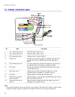


Summary of Product
Service Manual 4-11
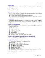
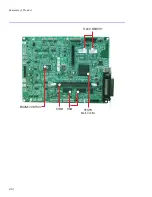
1) CPU BLOCK
A 120MHz - 32bit RISC processor is used to manage commands and data supplied by the host. This is converted
into a bitmap image which is passed to the engine block for printing.
2) SPGPm (Samsung Printer Graphics Processor) overview
■
Package: 272 pins PBGA
■
Power: 1.8V(Core), 3.3V(IO) power operation, P1284 inputs : 5V tolerant
■
Speed: 120MHz core ( ARM946ES) operation, 60MHz bus operation,
supportable engine speed: under 30ppm
■
Dual bus architecture for bus traffic distribution:
AMBA High performance Bus (AHB)
System Bus with SDRAM
■
Integrated ARM946ES: 32-bit RISC embedded processor core
■
Direct connection up to 5 SDRAM arrays:
SDRAM controller supports PC-66, PC-100 and PC-133 SDRAMs running at 60MHz
Up to 128MB per array, up to 512MB totally
Wide supports for various SDRAM configurations, including programmable band and column address
Programmable SDRAM refresh time interval
■
IEEE1284 compliant parallel port interface
Compatible ECP communications are supported
Direct support for IEEE1284 compliant data transceivers
■
High performance DMA based Interface to Printer Engine
■
Engine Controller
Motor Control Unit: Motor Speed Lookup Table Memory (128 x 16 x 2)
Pulse Width Modulation Unit
ADC Interface Unit
LSU Interface Unit
■
Ethernet Controller (MAC)
Full compliance with IEEE standard 802.3, 802.3u specification
Support 10/100 Mbps data transfer rates
USB 2.0
SDRAM
64MB
EEPROM
2048 bytes
Flash Memory
4MB
(W-LAN)
NOT SUPPORTED
Engine
Control
Bloc k
LPEC1
SDRAM DIMM
34MB~128MB
SPGPm
Panel
16x2 LCD
5 pin UART
Содержание Phaser 6100
Страница 1: ...Service Manual X XEROX P h a s e r C o l o r L a s e r P r i n t e r 6100 ...
Страница 2: ......
Страница 10: ...vi ...
Страница 22: ...Reference Information 2 6 ...
Страница 28: ...Specifications 3 6 ...
Страница 38: ...Summary of Product 4 10 RAM DIMM SPGPm Main Control FLASH MEMORY ENGINE CONTROL ...
Страница 44: ...Summary of Product 4 16 ...
Страница 66: ...Disassembly 6 10 3 Remove the toner caps and fit them to the inlets as shown below Toner Cap ...
Страница 84: ...Disassembly 6 28 7 Remove 5 screws 3 6 machine gold and then remove the HVPS Screw Screw Screw Screw Screw ...
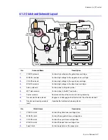
Страница 94: ...Disassembly 6 38 6 Disconnect 2 harnesses and remove the laser unit Harness Harness ...
Страница 130: ...Maintenance and Diagnostics 7 20 ...
Страница 188: ...Parts List 9 34 9 16 Base Frame Assembly 16 15 14 23 13 6 12 8 3 3 7 4 5 19 10 9 20 18 22 17 1 2 24 25 26 11 21 ...
Страница 190: ...Parts List 9 36 9 17 MPT Assembly 15 19 20 13 4 17 17 18 24 1 18 11 3 7 23 1 S5 6 2 S9 9 14 22 10 21 8 5 16 12 0 ...
Страница 196: ...Parts List 9 42 9 21 Transfer Belt Cam Assembly S18 9 0 8 S8 7 6 5 10 1 2 14 3 12 13 S8 11 4 ...
Страница 200: ...Parts List 9 46 ...


