


Troubleshooting
Service Manual 8-19
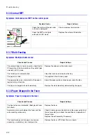
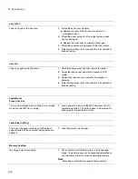
Main Motor Error
The main motor that drives the imaging unit, the
transfer belt and the pickup assembly is faulty.
1.
Open the DEVE cover and top cover, then check the
imaging unit and transfer unit.
■
Reseat or replace if defective.
2.
Open the rear cover and check (CN1) main motor
harness to (CN27) main board harness.
■
Reseat or replace if damaged.
3.
Verify power is supplied from the LVPS to the main board.
■
Replace the LVPS if the voltages are outside
specification.
4.
Replace the main board.
Waste Motor Error
This error is caused by a defective motor, open
circuit on the waste motor harness, or the motor is
stalling due to an increased waste motor torque
during operation.
1.
Open the front cover see if the waste toner cartridge is
full or the inlets are blocked with the toner.
■
Replace the waste toner cartridge and unblock waste
inlet feeds.
2.
Open the top cover and remove the transfer unit and
imaging unit to see if the imaging unit waste toner outlet
is blocked.
3.
Remove the front cover and check the waste motor
harness (CN2) DEVE_OEM to waste motor.
■
Reseat or replace if defective.
4.
Remove the HVPS cover and check the HVPS OEM
harness (CN2) to DEVE_OEM (CN1).
■
Reseat or replace if defective.
5.
Measure the voltage to CN2 Pin1 and Pin3 on
DEVE_OEM. (Normal : Over +10VDC)
■
Replace the DEVE_OEM.
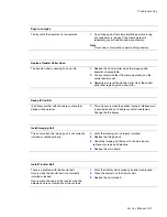
Transfer Belt Error
This is caused by an unseated or unlocked transfer
belt.
1.
Open the top cover and check that the transfer belt is
properly seated and locked in position.
■
Reseat and re-lock the transfer belt.
■
If the fault recurs replace the transfer beltt.
2.
Check the condition of the transfer belt harness
(especially if replacing the belt does not resolve the
problem).
■
Reseat or replace the harness if defective.
3.
Check the signal on Pin 1 (CN10) on the main board.
■
Replace the main board if the signal is low.
Содержание Phaser 6100
Страница 1: ...Service Manual X XEROX P h a s e r C o l o r L a s e r P r i n t e r 6100 ...
Страница 2: ......
Страница 10: ...vi ...
Страница 22: ...Reference Information 2 6 ...
Страница 28: ...Specifications 3 6 ...
Страница 38: ...Summary of Product 4 10 RAM DIMM SPGPm Main Control FLASH MEMORY ENGINE CONTROL ...
Страница 44: ...Summary of Product 4 16 ...
Страница 66: ...Disassembly 6 10 3 Remove the toner caps and fit them to the inlets as shown below Toner Cap ...
Страница 84: ...Disassembly 6 28 7 Remove 5 screws 3 6 machine gold and then remove the HVPS Screw Screw Screw Screw Screw ...
Страница 94: ...Disassembly 6 38 6 Disconnect 2 harnesses and remove the laser unit Harness Harness ...
Страница 130: ...Maintenance and Diagnostics 7 20 ...
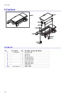
Страница 188: ...Parts List 9 34 9 16 Base Frame Assembly 16 15 14 23 13 6 12 8 3 3 7 4 5 19 10 9 20 18 22 17 1 2 24 25 26 11 21 ...
Страница 190: ...Parts List 9 36 9 17 MPT Assembly 15 19 20 13 4 17 17 18 24 1 18 11 3 7 23 1 S5 6 2 S9 9 14 22 10 21 8 5 16 12 0 ...
Страница 196: ...Parts List 9 42 9 21 Transfer Belt Cam Assembly S18 9 0 8 S8 7 6 5 10 1 2 14 3 12 13 S8 11 4 ...
Страница 200: ...Parts List 9 46 ...


