


Troubleshooting
8-22
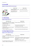
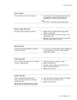
Jam at B, C
Paper is caught in the exit area
1.
Check the exit sensor actuator.
■
Replace the fuser if the exit sensor actuator is
damaged or bent.
2.
Check the paper guide rib of the output guide is clean
and not damaged.
■
Replace the fuser or exit assembly if damaged.
3.
Check the condition and operation of the fuser rollers.
4.
If the fault continues, refer to section 8.3.4 for additional
troubleshooting.
Jam at C
Paper is caught inside the printer.
1.
Open the duplex cover and then remove the paper.
2.
Check the feed sensor actuator and sensor in EDC
mode.
3.
Replace the feed sensor or actuator if damaged or
defective.
4.
If the fault continues, refer to section 8.3.3 for additional
troubleshooting.
Load Manual
Press Cont. Key
This is only displayed when printing in manual feed
mode and the MPT tray is empty.
1.
Load a sheet of media into the MPT and press the On-
line/continue button. The button needs to be pressed for
each page that needs to be printed.
Load [Size] in [Tray]
The size of the paper in the tray and the size of
paper required by the document being printed are
different.
1.
Load the correct size of paper.
Memory Overflow
Not enough memory capacity.
1.
The printer has insufficient memory to build the page
image. The print process will be cancelled automatically
and the printer will return to ready. Add more memory.
Note
Note
Note
Xerox does not currently support adding memory
Содержание Phaser 6100
Страница 1: ...Service Manual X XEROX P h a s e r C o l o r L a s e r P r i n t e r 6100 ...
Страница 2: ......
Страница 10: ...vi ...
Страница 22: ...Reference Information 2 6 ...
Страница 28: ...Specifications 3 6 ...
Страница 38: ...Summary of Product 4 10 RAM DIMM SPGPm Main Control FLASH MEMORY ENGINE CONTROL ...
Страница 44: ...Summary of Product 4 16 ...
Страница 66: ...Disassembly 6 10 3 Remove the toner caps and fit them to the inlets as shown below Toner Cap ...
Страница 84: ...Disassembly 6 28 7 Remove 5 screws 3 6 machine gold and then remove the HVPS Screw Screw Screw Screw Screw ...
Страница 94: ...Disassembly 6 38 6 Disconnect 2 harnesses and remove the laser unit Harness Harness ...
Страница 130: ...Maintenance and Diagnostics 7 20 ...
Страница 188: ...Parts List 9 34 9 16 Base Frame Assembly 16 15 14 23 13 6 12 8 3 3 7 4 5 19 10 9 20 18 22 17 1 2 24 25 26 11 21 ...
Страница 190: ...Parts List 9 36 9 17 MPT Assembly 15 19 20 13 4 17 17 18 24 1 18 11 3 7 23 1 S5 6 2 S9 9 14 22 10 21 8 5 16 12 0 ...
Страница 196: ...Parts List 9 42 9 21 Transfer Belt Cam Assembly S18 9 0 8 S8 7 6 5 10 1 2 14 3 12 13 S8 11 4 ...
Страница 200: ...Parts List 9 46 ...


