


Connection Diagram
Service Manual 11-1
11
Connection Diagram
Main Motor
DEV Motor
Power(AC Input, 220V/1
10V)
Switch3(Left Cover)
Switch1(Right Cover)
Switch2(Left Cover)
Developer_1st
Developer_2nd
Developer_3rd
Developer_4th
T1 Roller
T2 Roller
Charger Roller
D
eve
lo
p
e
r_
1
s
t
D
evel
o
p
e
r_
2
n
d
D
evel
o
p
e
r_
3
rd
D
e
vel
o
p
e
r_4
th
H.
V
(T
1
)
H.
V
(T
2
)
H.
V
(Ch
a
rg
e
r)
H.
V
(De
v
e
S
u
p
p
ly
)
Power Inlet & Switch
Solenoid(Deve 1st)
Solenoid(Deve 4th)
Solenoid(T1 Clean)
Clutch(Deve 1st)
Clutch(Deve 2nd)
Clutch(Deve 3rd)
Clutch(Deve 4th)
Solenoid(Deve 3rd)
Solenoid(Deve 2nd)
Main Motor
DEV Motor
W
aste Auger
Motor
*H.V = High V
oltage
C
M
Y
K
C
M
Y
K
C
M
Y
K
C
M
Y
K
N.C.
N.C.
C
N
7
C
N
30
C
N
28
C
N
14
C
N
2
5
C
N
3
C
N
2
C
N
4
C
N
9
C
N
6
C
N
8
C
N
1
1
C
N
1
2
C
N
2
6
C
N
1
6
C
N
2
1
C
N
3
1
C
N
3
3
C
N
2
3
C
N
3
2
C
N
2
4
C
N
1
9
C
N
1
0
C
N
1
7
C
N
1
5
C
N
5
C
N
27
C
N
29
CN
CN1
RS232
CN1
RS232
CN35
LSU
Fan
CN35
LSU
Fan
7
CN3
0
CN2
8
CN1
4
FUSER
DEVE
OEM KEY
HVPS
F
AN (FUSER)
Deve
Drive
LS
U
Control
Panel
CN
2
US
B
Parallel Port (IEEE 1284)
Ethernet (NPC)
Imaging Unit
Erase Lamp (Lower)
Erase Lamp
(Upper
, PTL)
CN1
CN1
T
ray 2
Se
n
s
o
r(
P
a
p
e
r
Em
p
ty
)
Se
n
s
o
r(
M
P
T
_
E
m
p
ty
)
S
e
ns
o
r(
F
e
e
d)
C
lu
tc
h
(F
eed
)
S
o
le
n
o
id
(P
ic
k
u
p
)
S
o
le
n
o
id
(M
P
T
)
S
o
le
n
o
id
(D
u
p
le
x
)
S
e
n
s
o
r(E
x
it)
T
ransfer Belt
S
e
n
s
o
r(W
a
s
te
S
e
n
s
or
(T
e
m
p. 1)
S
e
n
s
or
(T
e
m
p.
2)
CN2
5
CN3
CN2
CN4
CN9
CN6
C
N
13
CN1
3
CN8
CN1
1
CN1
2
CN2
6
CN1
6
CN2
1
CN3
1
CN3
3
CN2
3
CN3
2
CN2
4
CN1
9
CN1
0
CN1
7
CN1
5
S
o
le
n
o
id
(T
2
h
o
m
e
)
to
n
e
r)
CN5
CN2
7
CN2
9
Engine &
V
ideo
Controller
(MAIN Board)
Engine &
V
ideo
Controller
(MAIN Board)
LVPS
SMPS
LVPS
SMPS
FUSER
DEVE
OEM KEY
HVPS
Deve
Drive
CN1
C
O
N
4
C
O
N
1
C
O
N
2
C
O
N
3
CO
N4
CO
N1
CO
N2
CO
N3
C
N
1
V1,2,3
CN2
V4,5,6
V7,8,9
V10,1
1,12
CN1
V1,2,3
CN2
V4,5,6
V7,8,9
V10,1
1,12
C
N
1
(1
,2
)
C
N
2
T
1
T
Charger
Supply
2
C
N
1
C
N
6
C
N
2
C
N
7
C
N
3
C
N
8
C
N
4
C
N
9
C
N
5
C
N
1
0
V
1
C
N
1
1
T
A
B
1
V
2
V
3
V
4
CN1
(1
,2
)
CN2
T1
T
Charger
Supply
2
CN1
CN6
CN2
CN7
CN3
CN8
CN4
CN9
CN5
CN1
0
V1
CN1
CN1
1
TA
B
1
V2
V3
V4
H.V(1st Deve Supply)
H.V(2nd Deve Supply)
H.V(3rd Deve Supply)
H.V(4th Deve Supply)
37
1
2
3
8
9a
9b
9c
9d
7
12a
12b
12c
12d
13a
13b
13c
13d
4
5
6
10
15
14
11
16
36
35
34
33
32
38
31
30
29
28
27
26
25
24
23
22
21
20
19
18
17
Содержание Phaser 6100
Страница 1: ...Service Manual X XEROX P h a s e r C o l o r L a s e r P r i n t e r 6100 ...
Страница 2: ......
Страница 10: ...vi ...
Страница 22: ...Reference Information 2 6 ...
Страница 28: ...Specifications 3 6 ...
Страница 38: ...Summary of Product 4 10 RAM DIMM SPGPm Main Control FLASH MEMORY ENGINE CONTROL ...
Страница 44: ...Summary of Product 4 16 ...
Страница 66: ...Disassembly 6 10 3 Remove the toner caps and fit them to the inlets as shown below Toner Cap ...
Страница 84: ...Disassembly 6 28 7 Remove 5 screws 3 6 machine gold and then remove the HVPS Screw Screw Screw Screw Screw ...
Страница 94: ...Disassembly 6 38 6 Disconnect 2 harnesses and remove the laser unit Harness Harness ...
Страница 130: ...Maintenance and Diagnostics 7 20 ...
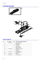
Страница 188: ...Parts List 9 34 9 16 Base Frame Assembly 16 15 14 23 13 6 12 8 3 3 7 4 5 19 10 9 20 18 22 17 1 2 24 25 26 11 21 ...
Страница 190: ...Parts List 9 36 9 17 MPT Assembly 15 19 20 13 4 17 17 18 24 1 18 11 3 7 23 1 S5 6 2 S9 9 14 22 10 21 8 5 16 12 0 ...
Страница 196: ...Parts List 9 42 9 21 Transfer Belt Cam Assembly S18 9 0 8 S8 7 6 5 10 1 2 14 3 12 13 S8 11 4 ...
Страница 200: ...Parts List 9 46 ...


