


Troubleshooting
8-10
8.3 Paper Feed Problems and Troubleshooting
8.3.1 Trouble with the Top Margin
Symptom: Printing begins at the wrong position on the paper (mis-registration?)
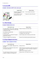
8.3.2 Jam at Tray 1 / Tray 2
Symptoms: Paper has not exited from the tray.
This jam occurs even though the paper feeds into the printer.
8.3.3 Jam at C
Symptoms: Paper is jammed in front of the fuser or under the transfer roller.
Possible Cause
Repair Actions
Wrong sensor timing caused by a
defective feed sensor actuator.
Replace the defective actuator.
Possible Cause
Repair Actions
Check the feed clutch and tray
clutch (pick solenoid) in EDC mode.
Replace any defective parts.
Check if the friction pad is loose or
missing in the tray.
Replace the tray.
Check the surface of the pick roller.
Is it dirty or damaged?
Clean or replace the pick roller.
Check the feed sensor in EDC
mode when the paper feeds into
the printer.
Replace the actuator, sensor, or main
board.
Possible Cause
Repair Actions
The paper is jammed in front of or
inside the fuser.
Replace the LVPS.
The paper is jammed in the exit
roller, the fuser and the feed sensor
area.
Clean the feed sensor.
Check the feed actuator and spring.
Check the feed and exit sensors in EDC
mode. Replace if defective.
Replace the main board.
Pick-up
Roller
Feed Sensor
Paper Empty Sensor
Exit Sensor
Feed Sensor
Содержание Phaser 6100
Страница 1: ...Service Manual X XEROX P h a s e r C o l o r L a s e r P r i n t e r 6100 ...
Страница 2: ......
Страница 10: ...vi ...
Страница 22: ...Reference Information 2 6 ...
Страница 28: ...Specifications 3 6 ...
Страница 38: ...Summary of Product 4 10 RAM DIMM SPGPm Main Control FLASH MEMORY ENGINE CONTROL ...
Страница 44: ...Summary of Product 4 16 ...
Страница 66: ...Disassembly 6 10 3 Remove the toner caps and fit them to the inlets as shown below Toner Cap ...
Страница 84: ...Disassembly 6 28 7 Remove 5 screws 3 6 machine gold and then remove the HVPS Screw Screw Screw Screw Screw ...
Страница 94: ...Disassembly 6 38 6 Disconnect 2 harnesses and remove the laser unit Harness Harness ...
Страница 130: ...Maintenance and Diagnostics 7 20 ...
Страница 188: ...Parts List 9 34 9 16 Base Frame Assembly 16 15 14 23 13 6 12 8 3 3 7 4 5 19 10 9 20 18 22 17 1 2 24 25 26 11 21 ...
Страница 190: ...Parts List 9 36 9 17 MPT Assembly 15 19 20 13 4 17 17 18 24 1 18 11 3 7 23 1 S5 6 2 S9 9 14 22 10 21 8 5 16 12 0 ...
Страница 196: ...Parts List 9 42 9 21 Transfer Belt Cam Assembly S18 9 0 8 S8 7 6 5 10 1 2 14 3 12 13 S8 11 4 ...
Страница 200: ...Parts List 9 46 ...


