4. Quick start
4.1. Minimal pin connections
UTXD
URXD
RTS/CTS
/RESET
ANT
RF
Host
Controller
Proteus -III
GND
VDD
1
5
1
2
4
WAKE_UP/BOOT/MODE_1
BUSY/LED_1/LED_2
6
7
3
SWD
IO
/S
WD
C
LK
8
VDD
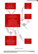
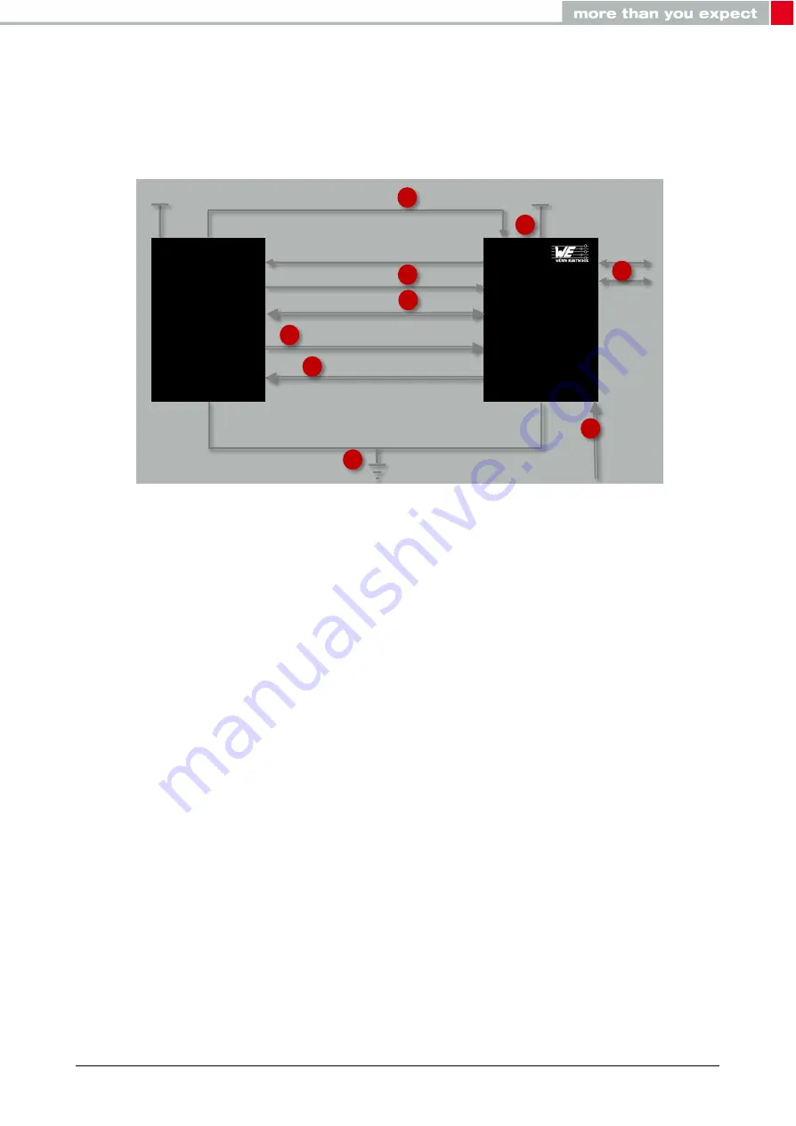
Figure 6: Minimal pin connections
The above image shows the steps to be performed to integrate the Proteus-III into a custom
end device.
1. Supply voltage and ground
Connect the
and
pins to supply the radio module with power.
2. UART serial interface to the host
Connect the UART pins
and
to the host to control the module via host.
3. UART flow control
In case of fast UART baudrates higher than 115.2 kbaud the UART flow control is
activated automatically. For lower data rates the flow control is inactive per default. If
activated the
and
pins must be connected to the host controller.
4. Antenna connection
The antenna configuration must be performed. See chapter
5. Reset
Connect the
pin to the host to allow a hard reset of the module.
6. (Optional) Wakeup from sleep, FOTA and mode selection
Proteus-III reference manual version 1.3
© August 2020
www.we-online.com/wireless-connectivity
23

