Weco Edge 550 Скачать руководство пользователя страница 120

Configuration...

Configuration of general operating parameters

Edge 580 - Edge 550

4-119

4.5.2.2.2 P

ROCEDURE


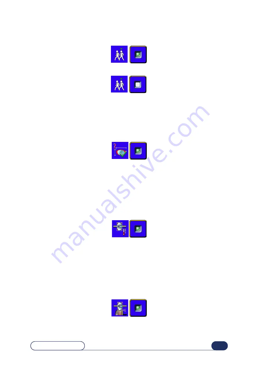
To select Novice operating mode : 


To select Expert operating mode : 

4.5.2.3 A

CTIVATING


RETOUCH


VERIFICATION

4.5.2.3.1 P

RINCIPLE

  >

At the beginning of a lens cycle, two points of the lens are checked to ensure that the lens fitted is the one 
you wish to retouch - right or left lens.

4.5.2.3.2 P

ROCEDURE


To select retouch verification :

4.5.2.4 A

CTIVATING


SIZE


COMPENSATION


ACCORDING


TO


TEMPERATURE

4.5.2.4.1 P

RINCIPLE

  >

The water temperature affects the degree of expansion of the wheels.

  >

Activating the temperature compensation automatically corrects for the expansion of the edging wheels and 
the lens due to water temperature variations.

  >

Activating the temperature compensation is 

strongly recommended

 if you work 

in closed circuit mode

.

4.5.2.4.2 P

ROCEDURE


To activate the temperature compensation :

4.5.2.5 A

CTIVATING


SIZE


COMPENSATION


ACCORDING


TO


WHEEL


LOADING

4.5.2.5.1 P

RINCIPLE

  >

A wheel becomes very abrasive after dressing. This can lead to some instability in the dimensions of edged 
lenses following wheel dressing.

  >

The wheel loading compensation function takes this effect into account and allows for compensation of the 
lens size after the wheel has been dressed.

4.5.2.5.2 P

ROCEDURE


To activate the loading compensation :

Содержание Edge 550

Страница 1: ...d keep it near the machine in order to be able to refer to it easily The information contained in this manual does not form a contract and can be modified without notice This document has been prepare...

Страница 2: ...Edge 580 Edge 550...

Страница 3: ...instructions with care Vital recommandation risk of machine damage and malfunctionning Follow the instructions with care Vital preliminary action Before undertaking any action check that the machine...

Страница 4: ...ng this product is disposed of correctly you will help prevent potential negative consequences for the environment and human health which could otherwise be caused by inappropriate waste handling of t...

Страница 5: ...Edge 580 Edge 550 1 5...

Страница 6: ...cases 3 79 Retouching a lens Applying an oversize to the lens Edging the left lens with different parameters from those of the right lens Edging several lenses identically Checking a finishing before...

Страница 7: ...Adjusting lens sizes Adjusting the flush of the mill bit Adjusting the axis with the Alta XL Adjusting the axis with the tool Adjusting the touch screen Consulting the setting values Consulting the st...

Страница 8: ...58 Illustration update 61 Illustration description update 62 Illustration description update 64 Illustration description update 66 Illustration update 68 Illustration update 70 Illustration update 72...

Страница 9: ...te 178 Description update 179 Description update 180 Description update 186 Description update 187 Description update 188 New page 201 Illustration description update 207 New page 208 New page 209 New...

Страница 10: ...1 INSTALLATION...

Страница 11: ...1 10 Edge 580 Edge 550 UNPACKING OF THE MACHINE 1 2 3 4 5 6 10 Keep the case the small box and the pipe near the machine...

Страница 12: ...person 2 Cut the two straps on the main carton 3 Cut the adhesive tape on the main carton 4 Check that the accessories small box case and tube have been supplied and keep them close to the machine 5 P...

Страница 13: ...Installation Unpacking the machine Edge 580 Edge 550 1 12...

Страница 14: ...TOR CLAMPING SCREWS 1 2 1 1 CONDITIONS Place the machine on the workbench You have space around the machine 1 2 1 2 PROCEDURE To remove the motor clamping screws follow the procedure below Flow chart...

Страница 15: ...Installation Removing external clamps Edge 580 Edge 550 1 14...

Страница 16: ...lustration 1 2 Removal of the shipping rails 1 With the help of a second person tip the machine gently to the rear so as to have access to the 4 rail fixing screws 2 Use a number 8 socket wrench to re...

Страница 17: ...Installation Removing the shipping rails Edge 580 Edge 550 1 16...

Страница 18: ...4 1 2 HOW To remove the machine cover follow the procedure below Flow chart 1 4 Removal of the covers As shown Illustration 1 3 Removal of the covers 1 4 2 REPLACING THE COVERS To replace the machine...

Страница 19: ...the internal clamps 4 2 3 REMOVAL OF THE TWO LENS FEELING SYSTEM CLAMPING SCREWS x2 headless Hc screws 6 OK UNCLAMPING OF THE CARRIAGE UNCLAMPING OF THE WHEEL UNIT Unscrew until the carriage moves fre...

Страница 20: ...emoving the covers 2 Unclip and remove the cover of the lens feeling system 3 Remove the headless nylon screws with a screwdriver and install them into their nearby holes 4 Remove the cover of the len...

Страница 21: ...Installation Removing the internal clamps Edge 580 Edge 550 1 20...

Страница 22: ...tallation 1 6 PREPARING THE BENCH 1 6 1 MACHINE DIMENSIONS The following illustrations show the machine dimensions Flow chart 1 6 Edger dimensions Height 570 mm Width 510 mm Depth 600 mm Weight 69 kg...

Страница 23: ...he bench and the openings which must be provided Position your machine correctly before drilling the bench Illustration 1 5 Positioning of the machine on the bench and drilling to be made USEFUL HINTS...

Страница 24: ...be easy to reach and closed when not in use Water pressure 4 7 bars Water discharge through a 100 mm diameter pipe The slope must be at least 5 to ensure proper evacuation of the refuse 1 7 1 2 FILTR...

Страница 25: ...nnections Edge 580 Edge 550 1 24 1 7 2 2 PROCEDURE As shown O pushed in and unlit mains plug disconnected 1 3 4 Level 2 5 7 8 Left hole 8 Settling tank 8 5 7 Left hole Filtration tank DIRECT WATER SUP...

Страница 26: ...osed 3 Remove the machine covers 4 Ensure that the machine is level screw or unscrew the four feet 5 Fit the drain pipe to the chassis 6 Fit the filter joint between the water supply connection and th...

Страница 27: ...Installation Water connections Edge 580 Edge 550 1 26...

Страница 28: ...s follows Flow chart 1 8 Electrical connections As shown Illustration 1 7 Electrical connections Note The pump and reader illustrations are not the property of Weco and are used purely as examples Wor...

Страница 29: ...Installation Electrical connections Edge 580 Edge 550 1 28...

Страница 30: ...ch OFF and mains plug disconnected 2 Reassemble the machine covers 3 Fit the lens clamping and lens holder adaptors on the shafts 4 Plug in the machine and switch on On Off switch lit 5 Start a dummy...

Страница 31: ...the edger Edge 580 Edge 550 1 9 2 SWITCHING THE MACHINE ON OFF Flow chart 1 10 Starting stopping of the machine To stop the machine press for 5 seconds then press the On Off switch Run 1 pushed in lit...

Страница 32: ...2 SAFETY PRECAUTIONS...

Страница 33: ...2 32 Edge 580 Edge 550...

Страница 34: ...he machine is not going to be used for a long period of time you should unplug the power cords from the wall outlet Unplug the machine if there is an electrical storm or when the machine is left unatt...

Страница 35: ...Safety precautions Safety Edge 580 Edge 550 2 34...

Страница 36: ...n is 100 blocking operations Use new adhesives Clean the visor regularly Make regular checks of the condition of the feeler tips and change them if they are worn chipped or damaged Before starting the...

Страница 37: ...2 36 Safety precautions Useful hints Edge 580 Edge 550...

Страница 38: ...3 UTILIZATION...

Страница 39: ...3 38 Edge 580 Edge 550...

Страница 40: ...ion 3 1 is an overall view Illustration 3 1 Overall view of the edger MAIN PARTS The exploded view below Illustration 3 2 shows the main parts of the edger Illustration 3 2 Exploded view of the edger...

Страница 41: ...1 Application screen 3 1 2 2 ZONE IDENTIFICATION The application screen below Screen 3 2 can be divided into zones Ecran 3 2 Identification of the application screen zones Vertical buttons Size choic...

Страница 42: ...scription of the use of the edger see General principles of use page 45 Astuce To see the icons associated wirh each menu button click on the numbered areas or on the buttons Ecran 3 3 Reading sequenc...

Страница 43: ...lisation of pull down menus chapter 4 Exemple IN THE TECHNICAL MENUS the choice button for selection of a function SEVERAL SELECTIONS ARE POSSIBLE You may activate one or more functions ONLY ONE SELEC...

Страница 44: ...ttons or menus appear in relief Exemple Buttons or menus which are activated or being activated are displayed in a yellow frame They are activated so long as the button is not released or the menu is...

Страница 45: ...Edge 550 Ecran 3 1 Main application screen Note The screen shown above is a montage to show all the basic functions available to the user from the main screen 2 3 4 Parameters 1 5 MAIN APPLICATION SC...

Страница 46: ...3 1 Standard procedure Open a job number Select the lens material Select the type of lens Select the type of finishing Select the sub finishing type Select the safety bevel if desired Selection polis...

Страница 47: ...e display zone The display is modified according to the job characteristics and the default configuration values Exemple If the lens material is specified in the data given to the edger e g Mineral it...

Страница 48: ...and the lens is fitted on the lens holder adaptor press briefly on this button R sultat the visor closes automatically the lens clamp shaft closes automatically the edging cycle is run 3 2 4 2 TO INT...

Страница 49: ...ass or sin gle safety bevel Max radius feeling if outlining hasn t been transmitted by the centering blocking device Lens roughing Form feeling Glass finishing Rimless or Bevel Glass polishing if sele...

Страница 50: ...ge one of the lenses the new characteristics will be memorised automatically and applied to the two lenses Attention Check the parameter values of the two lenses The lens characteristics material and...

Страница 51: ...Utilization General principles of use Edge 580 Edge 550 3 50...

Страница 52: ...b data are received page 49 and on the preference configuration see Personalisation of pull down menus chapter 4 Ecran 3 1 Main screen icons Bridge Right side Left side Superimposition Parameters Open...

Страница 53: ...he screen depend on the job data see When job data are received page 49 and on the preference configuration see Personalisation of pull down menus chapter 4 Ecran 3 2 Lens Material Icons High Index Pl...

Страница 54: ...hobic Specific cycle suitable for lenses with super hydrophobic treatment Hydrophobic Specific cycle suitable for lenses with hydrophobic treatment Fragile Specific cycle suitable for lenses that you...

Страница 55: ...TE The HD drilling will provide a high precision drilling quality notch axis and hole diame ters with the standard adhesive pads of the market Precision being the goal as a con sequence the drilling t...

Страница 56: ...e Icons Note The presence and the order of the icons displayed on the screen depend on the job data see When job data are received page 49 and on the preference configuration see Personalisation of pu...

Страница 57: ...ercentage Facette Chamfer according to machine Bevel or Mini bevel The apex of the facette chamfer according to machine bevel or mini bevel is positionned at a per centage of the lens thickness from t...

Страница 58: ...f the lens is less than 2 mm the applied bevel will automatically be of 1 2 1 2 type whichever bevel is selected More information about limits Click here or see Operating range page 97 Bevel Parameter...

Страница 59: ...ntage of the lens thickness from the front face Enter the desired percentage using the Parameters button Example If the middle of the groove is situated at 1 3 of the lens thickness from the front fac...

Страница 60: ...meter button Example groove of base 2 whose centre is situated at 3 mm from the front face at its closest point to the front face 3 3 5 2 2 GROOVE PARAMETERS Using this button go to the following para...

Страница 61: ...7 Groove Parameters Finishing Sub finishing Parameters Limits Description 5 00 to 5 00 mm Distance in mm between the front face of the lens and the middle of the groove 0 to 0 80 mm Depth of groove in...

Страница 62: ...job with drilling finishing page 73 Drilling normal to the front face of the lens Illustration Click here or see Producing a job with drilling finishing page 73 Drilling parallel to clamping shafts I...

Страница 63: ...reference configuration see Personalisation of pull down menus chapter 4 Ecran 3 9 Safety bevel Icons Safety bevel on front and rear faces of the lens available only if the facette chamfer hasn t been...

Страница 64: ...d but the safety bevel s will be machined or even removed More information about limits Click here or see Operating range page 97 Parameters of the safety bevel option Option Parameters Limits Descrip...

Страница 65: ...isplayed on the screen depend on the job data see When job data are received page 49 and on the preference configuration see Personalisation of pull down menus chapter 4 Ecran 3 10 Polishing Icons Wit...

Страница 66: ...re received page 49 and on the preference configuration see Personalisation of pull down menus chapter 4 Ecran 3 11 Lens edging Icons Oversize to boxing width Oversize to circumference Retouch to boxi...

Страница 67: ...f a job with a bevel Mineral lens Fragile type Bevel Finishing Rear face safety bevel Without polishing Here the job opened is n 2 Without oversize Bevel positionned according to a percentage to be en...

Страница 68: ...ut removing the block so as to be able to retouch it if necessary If you are unsure about the type of bevel positionning we advise you to choose Manual type from the main screen During the cycle when...

Страница 69: ...Production of a job with Rimless finishing Trivex lens Normal type Rimless Finishing Safety bevel on both faces With polishing Here the job opened is n 5 Without oversize Parameters accessible PRODUC...

Страница 70: ...iated with each step or obtain more details of the action required click on the object above or refer to the screen on the opposite page 3 4 2 3 HINTS When the edging cycle is finished remove the edge...

Страница 71: ...oove finishing Organic lens Hydrophobic type Groove finishing Groove positionned automatically Safety bevel on both faces With polishing Here the job opened is n 2 Oversize to circumference by 0 30 mm...

Страница 72: ...type of groove positionning we advise you to choose Manual type from the main screen During the cycle when the manual finishing screen is displayed press the Manual Groove button select the type of gr...

Страница 73: ...of a job with Drilling finishing PRODUCING A JOB WITH DRILLING FINISH Normal type Drilling normal to the front face With polishing Here the job opened is n Oversizing impossible No access to parameter...

Страница 74: ...ws Flow chart 3 6 Production of a job with Drilling finishing Astuce To familiarize yourself with the icons associated with each step or obtain more details of the action required click on the object...

Страница 75: ...type Groove positionned according to your chosen percentage With polishing Here the job opened is n Oversizing impossible Parameters accessible Safety bevels on front and rear faces Grooving finishing...

Страница 76: ...7 Production of a job with Grooving and Drilling finishing Astuce To familiarize yourself with the icons associated with each step or obtain more details of the action required click on the object abo...

Страница 77: ...an the diameter of the hole and you have confirmed the warning message Bit diameter hole diameter Do you wish to drill the hole diameter will be equal to the diameter of the bit A lens may be drilled...

Страница 78: ...he entire drilling plan will be ignored and no hole will be drilled The lens will be finished in rimless 3 4 6 1 HINTS When the edging cycle is finished remove the edged lens without removing the bloc...

Страница 79: ...Utilization Normal use Edge 580 Edge 550 3 78...

Страница 80: ...circumference or boxing width is indeed that which you wish to apply Note the difference between re edging a lens and retouching a lens Re edging corresponds to a second edging of the lens previously...

Страница 81: ...made at the circumference You can retouch the first lens after edging the second The retouch function is always accessible Exemple You have edges both lenses of the job and wish to apply a final retou...

Страница 82: ...t if necessary 3 5 2 3 HINTS Always check that the type of oversizing displayed circumference or boxing width is indeed that which you wish to apply 3 5 2 4 IMPORTANT NOTES The oversizing is applied t...

Страница 83: ...istics cannot be modified from one lens to another the lens material type of finishing the type of polishing You may only modify the following characteristics lens type sub finishing type safety bevel...

Страница 84: ...ristics 3 5 4 2 PROCEDURE Flow chart 3 11 Edging lenses with identical characteristics The lens is edged again with the same characteristics as the previous edging Astuce In this way you can group tog...

Страница 85: ...n allows you to visualize the finishing and modify its position if desired 3 5 5 2 PRESENTATION 3 5 5 2 1 MANUAL BEVEL SCREEN Ecran 3 1 Manual bevel screen IMPORTANT The indices of zones A and B indic...

Страница 86: ...as well Front face developed curve C Re feeling Movement of the index Angular position Index Groove centre developed curve Rear face developed curve Lens section at the position of the index Distance...

Страница 87: ...mfer will have a constant height on the whole perimeter of the lens C Re feeling Movement of the index Index position angulaire Front face developed curve Facette chamfer top developed curve Lens sect...

Страница 88: ...the same finishing angular position When you move one the other moves as well The height of the Facette Chamfer is adjusted side by side temporal nasal top bottom C Movement of the index Lens section...

Страница 89: ...nes A and B indicate the same finishing angular position When you move one the other moves as well The user defines the base of the Facette Chamfer C Movement of the index Lens section at the position...

Страница 90: ...you may have been redirected automatically to the manual finishing screen for the following reasons the bevel or the groove is outside the lens the bevel is too far back irregular points were detected...

Страница 91: ...reposition the whole finishing move it in one direction to the required position Then do the same from the opposite point 3 5 5 4 3 SPECIAL CASES After the lens feeling you may have been redirected a...

Страница 92: ...n the apex of the bevel and the front face is 5 mm The position of the bevel can be modified along four points top bottom temporal nasal Only the bevel apex is displaced along a point The opposite sid...

Страница 93: ...whose position you wish to modify Zone Press the chosen axis top bottom temporal nasal A Move the bevel apex and position it as you wish To the rear To the front Scan the lens profile as you wish Cloc...

Страница 94: ...ve is displaced along a point The opposite side remains fixed and the curve of the groove is unchanged If you wish to reposition all the groove move it in one direction to the required position Then d...

Страница 95: ...groove whose position you wish to modify Zone Press the chosen axis top bottom temporal nasal A Move the middle of the groove and position it as you wish To the rear To the front Scan the lens profil...

Страница 96: ...ns three times The lens is felt 0 5 mm closer to the interior each time If the three successive feeling operations are not enough the lens is too small and cannot be edged Confirm the message Complete...

Страница 97: ...Utilization Special cases Edge 580 Edge 550 3 96...

Страница 98: ...nses Edge 550 10000 lenses Edge 580 Polishing 6000 lenses Safety bevel 5000 lenses per wheel side Grooving 5000 lens Chamfering facetting Chamfering facetting finition 10000 lenses Edge 580 Bevelling...

Страница 99: ...0 2 mm at Boxing width Minimum distance between the apex of the bevel and the front rear face to make a safety bevel 1 6 mm Minimum distance between the front face of the lens and the front edge of t...

Страница 100: ...llustration 3 5 Limits of production of a bevel 3 6 2 3 FACETTE FINISHING Illustration 3 6 Limits of production of a facette Front face Rimless Min height of finished lens 17 75 mm Front face Min heig...

Страница 101: ...3 6 2 4 INCLINED GROOVE FINISHING Illustration 3 7 Limits of production of an inclinded groove Max angle 20 Max groove depth 0 8 mm Min diameter of finished lens 18 9 mm if depth 0 8 mm 18 5 mm if de...

Страница 102: ...those holes will be displayed in gray and simply pointed by the end of the drill bit tilted to maximum during the drilling phase this after acceptation of the marking by the operator the ring formed...

Страница 103: ...h front base and for high drilling radii distance from centre of block to centre of hole it is possible that the mill bit retaining nut may interfere with the lens If so the edger automatically limits...

Страница 104: ...4 CONFIGURATION...

Страница 105: ...4 104 Edge 580 Edge 550...

Страница 106: ...ht of the current screen If you are working with the Personalisation screen the edger will be displayed on the top right of the screen 4 1 1 2 ACCESS EXIT 4 1 1 2 1 TO OPEN THE SCREEN To reach the con...

Страница 107: ...RIPTION The personalisation menus access screen is shown below Ecran 4 2 Personalisation menus access screen 4 1 2 2 ACCESS EXIT 4 1 2 2 1 TO OPEN THE SCREEN 4 1 2 2 2 TO QUIT THE SCREEN Finishing def...

Страница 108: ...PTION The default parameters configuration screen is shown below Ecran 4 3 Default values configuration screen For a detailed description of the buttons see Sub finishings and associated parameters ch...

Страница 109: ...ered 4 2 4 LIMITS The information given in the tables below completes the values referred to in Using your Alta NX Application screen icons Sub finishings and associated parameters The default values...

Страница 110: ...AU 1 Sub finishing type Briot default value Lower limit Upper limit Incrementation 1 mm 5 mm 5 mm 0 01 mm 4 D 0 25 D 12 D 0 25 D 33 0 100 1 0 8 mm 0 8 mm 3 mm 0 1 mm TABLEAU 2 Sub finishing type Briot...

Страница 111: ...rs Edge 580 Edge 550 4 110 4 2 4 3 SAFETY BEVEL 4 2 4 4 DRILLING You must enter a base curve value within 0 25 D and 12 D TABLEAU 3 Type of safety bevel Briot default value Lower limit Upper limit Inc...

Страница 112: ...te acces to them the elements which must not be displayed because you do not need to use them Accordingly when the machine is started or when the job called up does not contain all the edging data the...

Страница 113: ...lise a menu press the corresponding button on the screen shown above R sultat A screen of the type shown below is displayed Ecran 4 5 Personalisation of pull down menus 2 x 3 To quit Functions that yo...

Страница 114: ...ew job To start an edging operation all the job criteria must have been selected No To be defined button can be maintained NOTA If you call up for a job including drillings with different drilling ang...

Страница 115: ...safety bevel processed to the front face of the lens Adjustment of the setting values RESET ONCE YOU HAVE SAVED THE LATEST ADJUSTMENTS To adjust the position of the top of the facette According to ma...

Страница 116: ...lues can affect the performance of the machine If you wish nonetheless to use the setting values adjustment function first target your needs with precision and then modify the values with full knowled...

Страница 117: ...Configuration Adjustment of the setting values Edge 580 Edge 550 4 116...

Страница 118: ...e machine s general operating parameters is shown below Ecran 4 3 Setting the parameters of the machine s general operating functions Configuration of the General operating parameters Modes Novice Exp...

Страница 119: ...this mode messages are displayed to inform advise and guide the user during the operations under way or to be undertaken This mode is intended for inexperienced operators or those wishing to be accom...

Страница 120: ...nsion of the wheels Activating the temperature compensation automatically corrects for the expansion of the edging wheels and the lens due to water temperature variations Activating the temperature co...

Страница 121: ...tends its working life According to your method of working you can decide how much time must elapse before the stand by mode is activated 4 5 2 7 2 PROCEDURE To enter your chosen delay 4 5 3 SAVE THE...

Страница 122: ...5 MAINTENANCE...

Страница 123: ...Maintenance Edge 580 Edge 550 5 122...

Страница 124: ...he current screen If you are working with the Maintenance screen the hand holding the spanner will be displayed on the top right of the screen 5 1 1 2 ACCESS EXIT 5 1 1 2 1 TO REACH THE DISPLAY To rea...

Страница 125: ...e maintenance menus access screen is shown below Ecran 5 2 Maintenance menus access screen 5 1 2 2 ACCESS EXIT 5 1 2 2 1 TO REACH THE DISPLAY 5 1 2 2 2 TO QUIT THE SCREEN To quit Changing the lens fee...

Страница 126: ...strations below will help you to identify the parts of the edger on which you will be working during maintenance operations Lens feeler tips Replacement Adjustment Visor Cleaning and replacement Swive...

Страница 127: ...Maintenance Visualize the components Edge 580 Edge 550 5 126...

Страница 128: ...tion of the lens feeler tips regularly and replace them as soon as they appear to be worn or damaged or every 3000 lenses Dress the wheels when a message asks you to do so Clean the removable visor re...

Страница 129: ...Maintenance Task list Edge 580 Edge 550 5 128...

Страница 130: ...cted when handling the lens holder and feeler tips 5 4 1 2 PROCEDURE To change the swivel adaptor blue pad follow the procedure below Flow chart 5 1 Changing the swivel adaptor blue pad As shown Illus...

Страница 131: ...550 Illustration 5 2 Changing the mill bit Mill bit Chuck nut Strut Block the rotation with an Allen key or a screwdriver Tighten Loosen the nut Flat organic lens Diametre 57 mm 10 00 205 Flushing po...

Страница 132: ...ll bit proceed as follows 1 2 3 4 5 Insert an Allen key or a screwdriver in the hole of the strut to block the rotation of the spindle 6 Fit an 8 mm spanner on the chuck nut 7 Loosen the nut with one...

Страница 133: ...3 HINTS During step 8 the bit may be difficult to remove from the chuck because of possible scale deposits In this case apply a small quantity of a common scale remover leave it for a few moments the...

Страница 134: ...Maintenance Regular maintenance of the edger Edge 580 Edge 550 5 133...

Страница 135: ...g the lens feeler tips FRAGILE MOUNTING Removable lens feeler tips 8 5 6 7 Place the feelers in the replacement position Place the feelers in the position to receive the tool Confirm and switch automa...

Страница 136: ...cedure below 1 2 3 4 5 Hold the holder and immobilize the feeler arm 6 Insert a screwdriver or an Allen key in the hole of the removable feeler tip 7 Tilt the right feeler tip carefully to unclip it 8...

Страница 137: ...NTS Always change the two removable feeler tips at the same time When you are handling the feeler tips take care not to put pressure on the feeler arms because that could alter the quality of the work...

Страница 138: ...Maintenance Regular maintenance of the edger Edge 580 Edge 550 5 137...

Страница 139: ...5 138 Edge 580 Edge 550 Illustration 5 3 Dressing a wheel 6 Ensure that the dressing disk is correctly centered using the indentations intended to receive the adaptors...

Страница 140: ...low to dress a wheel Flow chart 5 4 Dressing a wheel 5 4 4 3 HINTS Dress the wheels when a message asks you to do so 1 2 3 4 OR OR OR OR according to the wheel to be dressed 5 Make sure large adapters...

Страница 141: ...5 140 Edge 580 Edge 550 Illustration 5 4 Cleaning and replacing the removable visor 3 4 5 6 7...

Страница 142: ...Replacing the visor 5 4 5 4 HINTS Reguler cleaning of the visor increases the visibility of the interior of the edging chamber and the operations under way Operating in closed circuit mode affects the...

Страница 143: ...esentation of the tanks Illustration 5 6 Cleaning the drawer filter Illustration 5 7 Complete cleaning of the tanks and filters z Pump tank Settling tank also called main tank Drawer filter Decantatio...

Страница 144: ...endicular to the T 5 4 6 2 PROCEDURES Three situations are possible 5 4 6 2 1 FOR DAILY CLEANING Flow chart 5 7 Daily cleaning of the drawer filter 5 4 6 2 2 COMPLETE CLEANING OF THE TANKS AND FILTERS...

Страница 145: ...580 Edge 550 Complete cleaning of the tanks and filters cont 8 9 13 14 Pump connected to PUMP socket Water supply pipe connected to the valve Drain pipe placed above clean drawer filter Dump pipe val...

Страница 146: ...ons of the drain water supply and pump pipes Ensure that the discharge valve is closed If you have worked on the solenoid valves check the fixings 9 Remove the decantation tank carefully 10 Clean the...

Страница 147: ...ustration 5 8 Emptying the settling tank Illustration 5 9 Water connections Open Close the discharge valve Example of drainage system Discharge pipe 1 5 8 Discharge valve Here it is closed Supply conn...

Страница 148: ...llow the escape of any air which has remained in the pipes Close the valve before restarting the process Always check the water tightness of the unit before restarting the machine check the connection...

Страница 149: ...5 148 Edge 580 Edge 550 Ecran 5 3 Working in partial mode To quit...

Страница 150: ...e This operating mode allows you to disactivate an out of order element or function and continue to use the machine until the visit of a Briot technician When a function is disactivated the icon appea...

Страница 151: ...Maintenance Regular maintenance of the edger Edge 580 Edge 550 5 150...

Страница 152: ...375 If necessary Swivel Adaptor Small Size 11 90 406 If necessary Swivel Adaptor Small and flat 11 90 522 If necessary Chamfering facetting wheel Edge 580 Replaced by a technician only 15 77 418 Every...

Страница 153: ...Every 5000 lenses Mill bit SVS180105 1 hr of total drilling Emptying the settling tank if closed circuit operation cleaning of tanks and filters Every 500 lenses Visor 11 97 047 If necessary Filter ga...

Страница 154: ...own below Ecran 5 4 Setting menus access screen 5 6 1 2 ACCESS EXIT 5 6 1 2 1 TO REACH THE SCREEN 5 6 1 2 2 TO QUIT THE SCREEN Touch screen adjustment You are in the User Settings menu Consultation of...

Страница 155: ...5 154 Edge 580 Edge 550 Ecran 5 5 Lens feelers adjustment...

Страница 156: ...ngs Flow chart 5 11 Lens feeling adjustment 5 6 2 3 HINTS Always check that the adjusting tool n 14 04 301 is correctly fitted on the shaft You must neither force the fitting or feel any play The feel...

Страница 157: ...5 156 Edge 580 Edge 550 Illustration 5 10 Size adjustment Screen 1...

Страница 158: ...surements at 90 and record their average with the numeric keypad Perform the size adjustment procedure from beginning to end so as to record all the parameters 5 6 3 2 PROCEDURE Follow the steps below...

Страница 159: ...of the edge of the lens 21 22 If the apex of the bevel is off centre enter the value of the shift using the numeric key pad Apex too close to the rear face enter a negative value Apex too close to th...

Страница 160: ...size of the lens with a digital caliper 34 35 OR 36 37 Place the lens on the lens holder shaft again 38 39 At the end of the edging process open the lens holder shaft and remove the lens 40 Measure th...

Страница 161: ...must be in the centre of the edge of the lens 45 If the apex of the bevel is off centre enter the value of the shift using the numeric key pad Apex too close to the rear face enter a negative value A...

Страница 162: ...Maintenance Adjustments Edge 580 Edge 550 5 161...

Страница 163: ...5 162 Edge 580 Edge 550 Ecran 5 6 Adjustment of the flush of the mill bit...

Страница 164: ...automatically to this screen 5 6 4 2 PROCEDURE To adjust the mill bit flush proceed as follows Flow chart 5 13 Adjustment of the flush of the mill bit 5 6 4 3 HINTS Centre the lens n 10 00 205 in the...

Страница 165: ...5 164 Edge 580 Edge 550 Ecran 5 7 Adjustment of the axis setting with the Alta XL...

Страница 166: ...ner with the round black marking should be on the top right 6 Centre the adjustment lens in mode or 7 Fit a large block on the blocking head and block the lens If the message Lens too small do you wan...

Страница 167: ...XL 5 6 5 3 HINTS Always ensure that the pattern holder is clean and unscratched before placing the lens on it 16 Switch to the left shape of the lens and check that the drilling hole has been detecte...

Страница 168: ...Maintenance Adjustments Edge 580 Edge 550 5 167...

Страница 169: ...5 168 Edge 580 Edge 550 Ecran 5 8 Adjustment of the axis with the tool...

Страница 170: ...djustment 5 6 6 2 PROCEDURE To adjust the axis setting with the tool proceed as follows Flow chart 5 15 Adjustment of the axis setting with the tool 1 2 3 4 Remove the lens clamping and lens holder ad...

Страница 171: ...5 170 Edge 580 Edge 550 Ecran 5 9 Adjustment of the touch screen...

Страница 172: ...the screen 5 6 7 2 PROCEDURE Follow the steps below to adjust the touch screen Flow chart 5 16 Adjustment of the touch screen 5 6 7 3 HINTS Make sure that you press carefully on the cross being adjust...

Страница 173: ...5 172 Edge 580 Edge 550 Ecran 5 10 Example of a setting values screen Subject of the adjustment This is the lifting jack parameters screen Parameter value Parameter To reach the following display Exit...

Страница 174: ...fect for example The setting values cannot be modified from these displays 5 6 8 2 ACCESS EXIT BROWSING 5 6 8 2 1 TO ACCESS TO THE SCREENS 5 6 8 2 2 TO EXIT FROM THE SCREENS 5 6 8 2 3 TO NAVIGATE FROM...

Страница 175: ...Maintenance Adjustments Edge 580 Edge 550 5 174...

Страница 176: ...e The Statistics menu type is shown by the icon which is displayed on the top right of the current screen To quit Incident log Machine statistics You are in the Statistics menu List of Warnings Inform...

Страница 177: ...ONTENT The incident log may be consulted according to four themes consultation of the general list of incidents which have occurred events warnings and information consultation of the list of defect m...

Страница 178: ...incidents listed according to their occurrences For more information about an incident press the corresponding line The message appears The list shows the 128 messages displayed since the last update...

Страница 179: ...uches statistics based on user s maintenance statistics based on facette finishing according to machine 5 7 3 2 2 ACCESS EXIT You may access the desired statistics using the buttons shown above in the...

Страница 180: ...een for statistics based on the last wheel dressing is shown below Ecran 5 15 Consulting statistics based on the last wheel dressing Number of mineral lenses edged with bevel finishing Number of miner...

Страница 181: ...ased on the type of lens material Exemple According to the screen shown above 1114 CR39 lenses have been edged since the ma chine installation and 295 since the last wheel change and the average rough...

Страница 182: ...h bevel finishing have been edged since the machine installation and 57 with the wheel now fitted and the average edging time is 43 seconds per lens 915 lenses with rimless finishing have been edged s...

Страница 183: ...nishing and polishing have been edged since the machine installation and with the wheel now fitted and the average edging time is 40 seconds per lens 218 lenses with bevel finishing and polishing have...

Страница 184: ...he display screen for statistics based on safety bevel is shown below Illustration 5 14 Consulting statistics based on safety bevel Subject of the statistics Total number of lenses edged since the mac...

Страница 185: ...isplay screen for statistics based on groove finishing is shown below Illustration 5 15 Consulting statistics based on groove finishing Subject of the statistics Total number of lenses edged since the...

Страница 186: ...below Illustration 5 16 Consulting statistics based on drilling finishing Total number of lenses drilled since the machine installation Number of lenses drilled since the last bit change Average drill...

Страница 187: ...y screen for statistics based on the number of retouches is shown below Illustration 5 17 Consulting statistics based on the number of retouches Statistics based on the number of retouches Number of r...

Страница 188: ...user s maintenance is shown below Illustration 5 18 Consulting statistics based on user s maintenance Number of drillbit switches Number of lens feeling tips switches Finition wheel s number of dressi...

Страница 189: ...machine The display screen for statistics based on facettes Illustration 5 19 Consulting statistics based on facettes Number of chamfered facetted lenses since the machine has been put in operation N...

Страница 190: ...e loading another job 0x5 Unknown job number The job you are trying to load does not exist on the server Check the job number and load another number 0x7 Do you want to re edge the same lens You have...

Страница 191: ...b you have loaded calls for Polycarbonate lens material In the personalisation menus you have excluded this parameter so the edger cannot accept this job Confirm the message If you wish to load this j...

Страница 192: ...ded calls for Bevel curve finishing In the personalisation menus you have excluded this parameter so the edger cannot accept this job Confirm the message If you wish to load this job nonetheless modif...

Страница 193: ...e personalisation menus you have excluded this parameter so the edger cannot accept this job Confirm the message If you wish to load this job nonetheless modifiy the personalisation of the pull down m...

Страница 194: ...safety bevels on front and rear faces of the lens In the personalisation menus you have excluded this parameter so the edger cannot accept this job Confirm the message If you wish to load this job no...

Страница 195: ...job does not exist You have called up a job number but the corresponding job is not on the server Call up another number 0x101 No response from server wthin time limit You have tried to load a job bu...

Страница 196: ...hout the safety bevels NO the lens is not edged Remove the lens from the edging station 0x40A Front safety bevel groove will not be made Do you want to continue The front safety bevel and the groove c...

Страница 197: ...screen and proceed as required 0x416 Retouch impossible You have activated the retouch control and the lens detected does not match the parameters of the lens you wish to retouch Confirm the message R...

Страница 198: ...to do it now 800 mineral lenses have been edged with bevel finishing Finishing wheel dressing is recommended YES Dress the finishing wheel see Dressing a wheel chapter 5 NO You accept the risk of usin...

Страница 199: ...Edge 580 Edge 550 5 198 Maintenance...

Страница 200: ...6 TESTS...

Страница 201: ...6 200 Edge 580 Edge 550...

Страница 202: ...ow Ecran 6 1 Tests access screen Note SBGD safety bevel grooving drilling system Lens feeling You are in the Tests menu To quit Visor Opening closing Pump Touch plate Touch screen Temperature Voltmetr...

Страница 203: ...AL TEST SCREEN The following screen lens feeling test is typical of most tests see Operating principle chapter 6 x 2 Micro switch status Emergency stop TEST VALUES 1 5 2 3 2 4 You are in the lens feel...

Страница 204: ...art 6 1 Operating principle of a typical test screen 6 2 1 3 TEST SEQUENCE Tests must be undertaken in a logical sequence The tests which appear greyed cannot be carried out so long as the previous ac...

Страница 205: ...The following screen corresponds to the solenoid valve pump and extractor tests Ecran 6 1 Test screen with switch 6 2 2 1 2 PROCEDURE To start the test press the switch of the element you wish to tes...

Страница 206: ...ATION The following screen corresponds to the test screen for all micro switches and photocells Ecran 6 2 Test of micro switches and photocells 6 2 2 2 2 PROCEDURE Operate manually the micro switch or...

Страница 207: ...6 206 Tests Operating principle Edge 580 Edge 550...

Страница 208: ...7 CHEMISTRIE...

Страница 209: ...7 208 Edge 580 Edge 550...

Страница 210: ...ewear com This type of job is made in two steps Edging of the Rx lens with a blind hole in which the first magnet is glued Edging of the sun lens with the same shape as the Rx frame enlarged by 1 5 mm...

Страница 211: ...Chemistrie Presentation Edge 580 Edge 550 7 210...

Страница 212: ...shape is 1 1 so as to allow the superimposition of the frame on the screen This step and the following one can be substituted by the use of the and keys Call the job on wich the Chemistrie job has to...

Страница 213: ...e bridge s width is automatically calculated according to the Chemistrie manufactured bridge nose pieces Press the key Press the key two times Press the key Enter the oversize value wich will be appli...

Страница 214: ...8 TECHNICAL SPECIFICATIONS...

Страница 215: ...8 214 Edge 580 Edge 550...

Страница 216: ...king notches oblongs Drilling at variable angles parallel to the lens clamping shaft and lens holder shaft perpendicular to the front face perpendicular to the rear face Drilling grooving function Saf...

Страница 217: ...Technical Specifications Characteristics Edge 580 Edge 550 8 216...

Страница 218: ...Di 2002 95 EC directives EN 55022 Class B EN 61000 4 2 EN 61000 4 3 EN 61000 4 4 230 V 50 HZ EDGER Input voltage 200 V 250 V Power consumption 11 A Electric power 2300 W Fuses F1 et F2 20 AT Ferraz 2...

Страница 219: ...RoHs Di 2002 95 EC directives EN 55022 Class B EN 61000 4 2 EN 61000 4 3 EN 61000 4 4 230 V 50 HZ EDGER Input voltage 200 V 250 V Power consumption 7 A Electric power 1600 W Fuses F1 et F2 16 AT 250...

Страница 220: ...echnical Specifications Edge 580 Edge 550 8 219 THE MANUFACTURER CANNOT BE HELD RESPONSIBLE FOR DAMAGE CAUSED BY ANY USE OF THE MACHINE WHICH DOES NOT RESPECT THE INSTRUCTIONS IN THIS MANUAL OR DISPLA...

Страница 221: ...Technical Specifications Technical Specifications Edge 580 Edge 550 8 220...

Отзывы: