background image

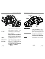
Before you begin, you should familiarize yourself with your WARN® Advanced Wireless Remote Control 

and each of its functions.

Advanced Wireless 
Remote Control:


The Advanced Wireless Remote Control allows the operator to control the winch 
and two auxiliaries. 

LCD:


Display of function menus, important vehicle feedback and winch functions.

Select Button:


Press to confirm/activate selections.

Left Button: 


Press to navigate left through each menu display.

Right Button: 


Press to navigate right through each menu display.

Winch Power-out Button:   

Press to control the power-out operation of the winch.

Winch Power-in Button:   

Press to control the power-in operation of the winch.

Reset Button

The reset button is used to restart your remote in rare cases when it functions 
incorrectly.  Resetting the remote will preserve your settings. 

USB Charging Port:   

Used to charge the internal battery.

USB Cable 

(not shown)

:  

Used to connect Advanced Wireless Remote Control to 
chargers or your computer to charge.

Car Charger Adapter

(not shown)

:


Car charger allows plugging into car’s DC socket to keep 
your Advanced Wireless Remote Control powered when 
you are on the go. 

Helpful Hint: 

 Connect your remote 

to a charging device now.  

This  will allow your remote 

to charge while you are 

installing your winch.  Refer 

to page 13 for charging 

steps.

USB Charging Port


WARN INDUSTRIES  


11

KNOW YOUR ADVANCED WIRELESS REMOTE

LCD

Right

Button

Select

Button

Winch

Power-in

Button

Winch

Power-out

Button

Left

Button

Reset

Button

Mounting Orientation and Hardware

Feet down mounting:

•  (

4

) M10 -1.5   anged hex locknut

•  (

4

) M10-1.5 x 35 hex   ange, 8.8, bolt 

•  (

2

) 7/16-14 x 1 hex bolt 

For feet forward mounting:

•  (

4

) M10x1.5   anged locknut 15mm hex

•  (

4

) M10-1.5 x 35 hex   ange, 8.8, bolt 

•  (

2

) M10-1.5 x 40 hex   ange, 8.8, bolt


(found               

in separate plastic bag)

Step 1 - Mount the Winch

Winch mounting kits are available to satisfy nearly 
all applications.  For information on available kits, 
contact your WARN® product dealer.

NOTICE  For optimal performance and the results you expect, 

WARN® mounting plates are strongly recommended.

 CAUTION

 To prevent accidental activation of the winch 

and serious injury, complete the winch installation and attach 
the hook before installing the wiring.  

WARNING 

 Always choose a mounting location that is 

suffi  ciently strong enough to withstand the maximum pulling 
capacity of your winch.

WARNING

 Never use bolts that are too long.

WARNING

 Always spool the winch rope onto the drum 

in the direction speci  ed by the drum rotation labels on the 
winch and/or in the documentation.  This is required for the 
automatic brake (if so equipped) to function properly.

WARNING

 Always wind the winch rope on the bottom 

(mount side) of the drum.

This winch should always be mounted in a 

horizontal orientation with the rope winding on 
and off the drum on the mount side (bottom) of the 
drum.  

Correct rotation is required for the automatic 

brake to function properly.  Horizontal mounting 
helps prevent the rope from piling up on one end of 
the drum which can damage the winch.

 Always use recommended bolt and washer 

combinations torqued to recommended levels. 
Specifications listed below.  Mounting system will 
dictate bolt length.

Mounting Bolt Pattern: 

Standard:    10”x 4.5”  (54 mm x 114.3 mm)
Smooth and   at mounting surface, minimum 
thickness = 1/4” (6.4 mm)

(2) M10-1.5 x 35

(2) M10-1.5 x 40

(found in separate bag)

(4) M10-1.5   anged hex 

locknut 

(4) M10-1.5   anged  hex 

locknut 

(4) M10-1.5 x 35 

 anged hex bolt

(2) 7/16-14 x 1 hex 

bolt


WARN INDUSTRIES  


12

MOUNTING 

92821A4

92821A4

Содержание ZEON

Страница 1: ...ce Service Clients 1 800 543 9276 2016 Warn Industries Inc WARN the WARN logo are registered trade marks of Warn Industries Inc WARN et le logo WARN sont des marques d pos es de Warn Industries Inc ZE...

Страница 2: ...English 1 Fran ais 25 Espa ol 49 92821A4 92821A4...

Страница 3: ...ly Product Specification and Performance Data Provides product specifications performance data and replacement parts information Other product literature specific to some products Go to www warn com c...

Страница 4: ...Rope Over Top of Drum Fairlead Pinch Point Hot Surface Hazard Fire and Burn Hazard Never Route Electrical Cables through or near Moving Parts Hazard Exposed Wiring Hazard Insulate Exposed Wiring and T...

Страница 5: ...anceforeachantenna typeindicated Antennatypesnotincluded inthislist havingagain greaterthan themaximumgain indicatedforthattype arestrictly prohibited forusewiththisdevice WARN INDUSTRIES 5 GENERAL SA...

Страница 6: ...bythe installation instructions Neverlean over battery whilemakingconnections Neverroute electricalcables overbattery terminals Nevershort battery terminals with metalobjects Alwaysverifyarea is clear...

Страница 7: ...allows for engagement and disengagement of the clutch with the Advanced Wireless Remote Control Control Pack Using electrical power from the vehicle s battery the control pack s contactor switches po...

Страница 8: ...hex bolt For feet forward mounting 4 M10x1 5 anged locknut 15mm hex 4 M10 1 5 x 35 hex ange 8 8 bolt 2 M10 1 5 x 40 hex ange 8 8 bolt found in separate plastic bag Step 1 Mount the Winch Winch mounti...

Страница 9: ...ingAmps Route battery connection cables in areas which will not cause them to chafe or cut through the insulation causing a potential short circuit The winch power wire must be routed to the battery A...

Страница 10: ...tor in the upper right corner of the menu indicating the remote is charging 4 The remote is fully charged when the battery indicator icon is filled NOTE Allow a minimum of two hours for battery to ful...

Страница 11: ...If clutch does not engage when requested a warning error will display within the clutch status icon See Trouble Shooting section in this manual for possible solutions WINCHING WARNING Alwayswearheavyl...

Страница 12: ...liary 1 Auxiliary 2 Select Auxiliary 1 Linked WARN INDUSTRIES 20 FIRST TIME OPERATING INSTRUCTIONS Link Auxiliary HighBeam With your Advanced Wireless Remote you are able to link your auxiliaries to y...

Страница 13: ...ack of the control pack to OFF and then ON again 6 If pairing is successful a green check mark will appear 7 If pairing was unsuccessful the red X mark will remain and the remote will remain unpaired...

Страница 14: ...your winch and its operations X Check fasteners and make sure they are tight and to proper torque Replace damaged fasteners X X Verify wiring to all components is correct and be certain that all conne...

Страница 15: ...es de performance Fournit les caract ristiques du produit les donn es de performance et les renseignements concernant les pi ces de rechange Autres documents relatifs des produits sp cifiques Consult...

Страница 16: ...l extr mit ou le loquet du crochet Ne jamais enrouler le c ble sur le dessus du tambour Point de pincement du guide c ble Risque de surface chaude Risque d incendie et de br lure Ne jamais faire passe...

Страница 17: ...l appareilet l enroulementouled roulementduc ble Toujourspositionnerleguide c bleavecl avertissement visiblesurledessus Toujours tirer aupr alablelec bleetl enroulersouscharge avant del utiliser Unc b...

Страница 18: ...crochetmunid unloquet Toujours s assurer que l op rateuretles personnes pr sentes sontconscientsde la stabilit du v hicule et ou de la charge Ne jamaisaccrocherlec ble lui m me AVERTISSEMENT WARN INDU...

Страница 19: ...sant le courant de la batterie du v hicule le contacteur du coffret de commande commute l alimentation vers le moteur permettant ainsi l op rateur de changer le sens de rotation du tambour Pour des ap...

Страница 20: ...onal 7 16 14 Montage des pieds vers l avant 4 Contre crou M10x1 5 15 mm hexagonal 4 boulon embase hexagonale M10 1 5 x 35 8 8 2 boulon embase hexagonale M10 1 5 x 40 8 8 fourni part dans un sachet en...

Страница 21: ...ation et de cr er des risques de court circuit Le c ble d alimentation du treuil doit passer par la batterie Il est obligatoire d avoir une connexion directe de l alimentation la batterie rouge et un...

Страница 22: ...trique Menu principal Activer la t l commande en appuyant sur n importe quel bouton Le menu principal s affiche automatiquement partir du menu principal vous pouvez acc der aux quatre op rations Quatr...

Страница 23: ...tions possibles UTILISATION DU TREUIL AVERTISSEMENT Toujoursporterdesgantsdecuir pais durantla manipulationduc bledutreuil AVERTISSEMENT Ne jamaisd passerl e orten1 re couchedutreuil AVERTISSEMENT Tou...

Страница 24: ...non reli Bouton de s lection Auxiliaire 1 Auxiliaire 2 Bouton de s lection Auxiliaire 1 reli WARN INDUSTRIES 44 INSTRUCTIONS RELATIVES UNE PREMI RE UTILISATION Relier les syst mes auxiliaires aux pha...

Страница 25: ...dant 3 secondes pour afficher le menu de confirmation de l appairage 3 Pour continuer l appairage s lectionner l ic ne de la coche verte en d pla ant le curseur au moyen des boutons droite ou gauche p...

Страница 26: ...on fonctionnement X V ri er les xations et s assurer qu elles sont bien serr es aux couples de serrage indiqu s Remplacer toute xation endommag e X X V ri er que chaque composant est correct et que to...

Страница 27: ...ficaciones del producto y datos de rendimiento Proporciona especificaciones del producto datos de rendimiento e informaci n sobre piezas de repuesto Otra documentaci n del cabrestante espec fica para...

Страница 28: ...ble en la parte superior del tambor Punto de pellizco de la gu a del cable Peligro de super cie caliente Peligro de incendio y quemaduras Nunca pase los cables el ctricos por partes m viles o cerca de...

Страница 29: ...araremolcar Las cargasbruscaspuedenda ar sobrecargar o romperel cable Nousenunca elcabrestante para aseguraruna carga Noponga nunca en funcionamiento este cabrestante si se encuentra bajo losefectosde...

Страница 30: ...i ns loa la positiva elbornede labater a Conectesiemprenegrodelatierra elcabledealimentaci n s loalterminalnegativo delabater a Nuncaconecteelrojo elcabledealimentaci nalterminal negativo delabater a...

Страница 31: ...ue con el control remoto inal mbrico avanzado Paquete de control Los contactores del paquete de control transmiten corriente al motor utilizando la energ a el ctrica de la bater a del veh culo Esto pe...

Страница 32: ...x 1 Para montaje con los pies hacia adelante 4 Contratuerca tap n M10x1 5 de 15 mm hexagonal 4 Brida hexagonal M10 1 5 x 35 perno 8 8 2 Brida hexagonal M10 1 5 x 40 perno 8 8 suministrado en bolsa pl...

Страница 33: ...No instale los cables de la bater a donde puedan desgastarse debido al roce o sufrir cortes en el material aislante produci ndose as un cortocircuito El hilo de alimentaci n del cabrestante debe pasar...

Страница 34: ...de inicio Desde el men de inicio puede acceder a cada una de las cuatro funciones Cuatro funciones 1 Accionamiento del cabrestante 2 Auxiliar 3 Ajustes del sistema 4 Apagar 1 Utilice los botones de i...

Страница 35: ...esoluci n de problemas de problemas de este manual para posibles soluciones ACCIONAMIENTO DEL CABRESTANTE ATENCI N Utilicesiempreguantesgruesosde cueropara manipularelcable delcabrestante ATENCI N No...

Страница 36: ...1 conectado WARN INDUSTRIES 68 INSTRUCCIONES DE PRIMER FUNCIONAMIENTO Conectarsistema auxiliara luces de carretera Con su control remoto inal mbrico avanzado puede conectar sus sistemas auxiliares a...

Страница 37: ...y el bot n derecho a la vez durante 3 segundos para acceder el men de confirmaci n de emparejamiento 3 Para continuar el emparejamiento seleccione el icono de verificaci n verde con el bot n de derech...

Страница 38: ...l uso del cabrestante para comprender el funcionamiento y el manejo del cabrestante X Compruebe las sujeciones y aseg rese de que est n bien apretadas y que el torque es el apropiado Sustituya todos l...

Отзывы: