background image

WP1624 Series 
Firewood Processor

Introduction

7

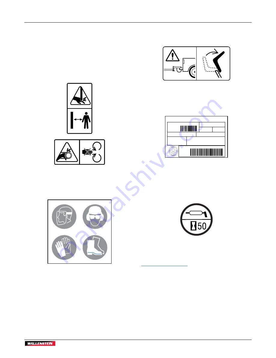
1.4  Types of Decals on the Machine

When getting familiar with the Wallenstein product, notice that 
there are numerous decals located on the machine. There are 
different types of decals for safety, information, and product 
identification. The following section explains what they are for 
and how to read them. 

Safety Decals

 have a yellow background and are generally two 

panel. They can be either vertical or horizontal. 

Safety Notice 

decals have a blue background and are generally 

rectangular with single or multiple symbols. This decal shows 
suggested PPE requirements for safe operation. 

Informative 

decals have a white background and can vary in the 

number of panels. These decals provide operating information 
on a feature of the machine. 

Product 

decals are associated with the product and carry 

various messages such as model, serial number, and 
manufacturer.

VIN/

NLV:

MODEL: ##########

#########

Manufactured by:

 Wallenstein Equipment Inc., 7201 Line 86, Wallenstein ON N0B2S0, Canada

TYPE OF VEHICLE/TYPE DE VEHICLE:

TRA / REM

GAWR/PNBE (KG): GVWR/PNBV (KG):

###

DIMENSION- RIM/JANTE

/

E

R

I

T

 :

PNEU:

COLD INFL. PRESS/PRESS DE

CONFLA A FROID (PSI/LPC):

THIS VEHICLE CONFORMS TO ALL APPLICABLE STANDARDS

PRESCRIBED UNDER THE CANADIAN MOTOR SAFTEY REGULATIONS

IN EFFECT ON THE DATE OF MANUFACTURE / CE VEHICLE EST

CONFORME A TOUTES LES NORMES QUI LUI SONT APPLICABLES EN

VERTU DU REGLEMENT SUR LA SECURITE DES VEHICLES

AUTOMOBILES DU CANADA EN VIGUEUR A LA DATE DE SA FABRICATION.

###

###

###

###

Maintenance 

decals have a green background. They can have 

various messages and vary in the number of panels. These 
decals indicate the maintenance type and can indicate the 
service interval. Maintenance decals are further explained in the 
Service and Maintenance section. 

For complete illustrations of decal locations on the machine, 
download the parts manual for this product model at 

WallensteinEquipment.com

.

Содержание P3 PULSE WP1624

Страница 1: ...OPERATOR S MANUAL Firewood Processor S N 2E9US1118NS080079 and up 01440 WP1624 Series Part Number Z97106_En Rev Sep 2022 TECHNOLOGY...

Страница 2: ...the Fuel Level 43 8 3 Check the Engine Oil Level 43 8 4 Check the Hydraulic Oil Level 44 8 5 Check the Chain Saw Bar Oil Level 44 8 6 Check the Saw Chain 44 8 7 Machine Break In 45 9 Operating Instruc...

Страница 3: ...fications 76 14 1 Machine Specifications 76 14 2 Conveyor Specifications 77 14 3 Machine Dimensions 78 14 4 12 ft Conveyor Dimensions 79 14 5 24 ft Conveyor Dimensions 80 14 6 Common Bolt Torque Value...

Страница 4: ...king conveyors is available as well as trailer type conveyors in 16 ft 4 8 m and 24 ft 7 3 m lengths Logs are set onto the live deck and deck chains carry them to the infeed conveyor The conveyor move...

Страница 5: ...warranty policy and have reviewed the manuals Dealer Address City State Province ZIP Postal Code Phone Number Dealer Inspection Checklist Engine Starts and Runs All Valve Controls Function All Cylind...

Страница 6: ...stein product when ordering parts or requesting service or other information The Serial Number Plate location is shown in the illustration For future reference record your product Serial Number in the...

Страница 7: ...various messages such as model serial number and manufacturer VIN NLV MODEL Manufactured by Wallenstein Equipment Inc 7201 Line 86 Wallenstein ON N0B2S0 Canada TYPE OF VEHICLE TYPE DE VEHICLE TRA REM...

Страница 8: ...ates a potentially hazardous situation that if not avoided may result in minor or moderate injury It may also be used to alert against unsafe practices IMPORTANT To avoid confusing equipment protectio...

Страница 9: ...nt in any way Unauthorized modifications may affect the integrity of the machine or the ability of the machine to perform as designed Modifications can impair safety or function They can affect the li...

Страница 10: ...vent slipping and tripping Keep working area clean and free of debris Stop engine if leaving the machine unattended Make sure all guards deflectors and shields are installed before starting and operat...

Страница 11: ...ake sure the procedure is understood before performing any service work 2 6 2 Hydraulic System Safety Make sure that all the components in the hydraulic system are kept clean and in good condition Mak...

Страница 12: ...lyte immediately Avoid contact with battery posts terminals and related accessories They contain lead and lead compounds chemicals known to cause harm Wash hands immediately after handling Keep all sp...

Страница 13: ...ial to be welded and select the correct welding procedure and materials electrodes rods wire that provide a weld metal strength equivalent to the parent material Work with extra care when welding grin...

Страница 14: ...present 4 Operator Zone Only the operator should be in the Operator Zone Follow these important points to keep bystanders and workers safe from hazards Establish a Safe Zone perimeter around the work...

Страница 15: ...ed in this manual Do not use or allow anyone else to use this machine until such information has been reviewed Review this information annually before the season start up Make these periodic reviews o...

Страница 16: ...ed a new safety sign must be applied W100 Practicing good safety means becoming familiar with safety signs decals and warnings and being aware of situations that require alertness The top panel or lef...

Страница 17: ...Safety Signs WP1624 Series Firewood Processor Safety 17 3 1 Safety Sign Locations Numbers correspond with the Safety Sign Explanations on page 23 Fig 3 Safety Decal Locations 1 2 3 4 4 4 4 7 6 5...

Страница 18: ...WP1624 Series Firewood Processor Safety 18 Safety Signs 0 4 3 9 10 5 14 8 13 15 Fig 4 Safety Decal Locations...

Страница 19: ...Safety Signs WP1624 Series Firewood Processor Safety 19 4 6 7 8 9 10 10 12 1 8 8 3 2 10 Fig 5 Safety Decal Locations See the Operator Panel Layout on page 32...

Страница 20: ...WP1624 Series Firewood Processor Safety 20 Safety Signs 1 4 11 16 4 4 17 10 17 4 16 11 4 Fig 6 12 ft Conveyor Safety Decal Locations...

Страница 21: ...Safety Signs WP1624 Series Firewood Processor Safety 21 16 4 17 4 1 4 8 Fig 7 24 ft Conveyor Safety Decal Locations...

Страница 22: ...WP1624 Series Firewood Processor Safety 22 Safety Signs 1 10 4 6 19 9 1 10 4 18 16 4 17 8 Fig 8 24 ft Conveyor Safety Decal Locations Continued...

Страница 23: ...personal injury resulting from contact with chain saw Keeps hands clear 4 Warning Risk of hands being pinched or caught in drive chain resulting in serious injury Keeps hands clear of this area 5 Warn...

Страница 24: ...Warning Risk of high pressure hydraulic fluid piercing exposed skin Do not check for leaks with hand or fingers Serious injury can result 11 Warning Risk of injury from falling equipment Install latch...

Страница 25: ...ys replace safety signs that are missing or have become illegible Safety signs are available from your local Wallenstein Equipment dealer or distributor Keep the safety signs clean and legible at all...

Страница 26: ...program can provide many years of trouble free service IMPORTANT Make sure all operators understand how to put the machine in a safe service position before servicing or repairing See page 10 4 2 Job...

Страница 27: ...g 16 WP1624 Components 1 Splitting wedge assembly 2 Hand jack rear 3 Axle full flex 4000 lb electric brakes 4 Tires ST225 75R15 LRE 5 Chain saw oil reservoir 6 Top roller assembly 7 Engine Vanguard 29...

Страница 28: ...WP1624 Components Continued 15 Conveyor hydraulic control valve 16 Block dropper 17 Chain saw 18 Safety whip 19 Infeed conveyor 20 Infeed conveyor chain 21 Trailer hitch 22 Trailer hand jack 23 Live d...

Страница 29: ...y applies to a WP1624 12 1 2 3 4 5 6 7 8 9 10 11 12 Fig 18 12 ft Conveyor Components 1 Conveyor pivot 2 Chute lock arm 3 Folding frame 4 Wheels 5 Conveyor chain 6 Hydraulic motor 7 Conveyor chain link...

Страница 30: ...624 24 1 2 3 4 5 6 7 8 9 10 11 12 13 14 15 1 Conveyor hopper 2 Conveyor chain 3 Chain cleats 4 Conveyor trough 5 Hydraulic motor 6 Upper folding frame 7 Hand winch 8 Winch cable 9 Toplink 10 Lower fol...

Страница 31: ...the on run position at the detent This is the position where the engine operates STOP START Turn fully clockwise to engage the starter solenoid and start the engine Release the key when the engine sta...

Страница 32: ...r is fully retracted 2 Splitter Circuit Hydraulic Pressure Gauge This gauge indicates the splitter cylinder circuit operating pressure 5 2 Operator Panel Hydraulic Controls 01866 4 2 3 1 5 6 7 8 Fig 2...

Страница 33: ...nveyor Push the lever forward to feed logs onto the infeed conveyor Pull the lever back to reverse the live deck 7 Chain Saw Circuit Hydraulic Pressure Gauge This gauge indicates the saw circuit opera...

Страница 34: ...for conveyors that are optional equipment An integrated 12 ft 3 6 m is pinned to the rear of the machine A self contained hydraulic 24 ft 7 3 m conveyor stands separately from the machine Conveyor co...

Страница 35: ...ng unsafe 3 Red The working angle is unsafe 4 White The conveyor is in the travel position 5 4 4 12 ft Conveyor Pivot The 12 ft conveyor can pivot up to 50 degrees on both sides of the machine 00385 F...

Страница 36: ...parking brake The switch is there to safely stop the trailer in the event it becomes accidentally disconnected from the tow vehicle Using it as a parking brake when un hooked drains the machine s batt...

Страница 37: ...n IMPORTANT The live deck locking pins must be pinned in place to prevent the live deck from moving during operation Support Legs 4 Remove the hitch pins and swing both support legs under the live dec...

Страница 38: ...ndent of each other If the log does not fall squarely into the splitting hopper adjust as required 1 First try setting one strut as active Lift the block dropper paddle 1 and slide the end of one stru...

Страница 39: ...spring loaded indicator can be locked at any desired position along the slide For reference follow the decal on the back of the splitter hopper or use the vertical slotted holes in the back plate Each...

Страница 40: ...pin from the conveyor hitch 4 Disconnect the toplink pin if connected and place it in the stored position 01850 Fig 32 Toplink Pin 5 Set the conveyor height as required For instructions see page 40 6...

Страница 41: ...applies to a 12 ft conveyor only 1 Remove the snap lock pin 2 Push the conveyor to the required angle 3 Insert the snap lock pin to secure the conveyor 00385 Fig 36 Set the Conveyor Angle 7 5 Move th...

Страница 42: ...elds are in place secured and functioning as designed Check and tighten all fasteners Make sure equipment is working and in good repair Check for hydraulic leaks Tighten fittings or replace components...

Страница 43: ...ine manual for additional information on fuels Procedure 1 Clean the area around fuel tank cap Fill the tank to 1 2 12 mm below bottom of filler neck to provide space for any fuel expansion Do not ove...

Страница 44: ...ean the area around filler cap and remove it 2 Use a clean funnel and add oil until the level just fills the sight glass window 3 Install filler cap securely Wipe up any spilled oil Check levels after...

Страница 45: ...der transporting new and newly sharpened saw chain to and from the job site in a container with lubricant 1 Lubricate your saw chain prior to use 2 Increase saw speed gradually over the first 2 4 minu...

Страница 46: ...pping Procedure 1 Stop cutting and splitting logs Clear all split wood out Let hydraulic controls go to their neutral position 2 Move the throttle to idle position to slow the engine speed and allow i...

Страница 47: ...6 ft 1 8 m load them from the other side Do not stack logs Try to keep logs square with the deck rails Always load logs with the bigger end of the log towards the saw Place logs on the live deck so we...

Страница 48: ...om the operator 00397 Fig 47 Advance Log 00398 Fig 48 Log Stop Guide 9 5 Top Roller A hydraulic motor powers the top roller to work in series with the infeed conveyor It assists feeding logs into the...

Страница 49: ...llow adequate time during start up for bar oil to reach the chain 00388 Fig 53 Bar Oil IMPORTANT In cold weather run the saw slowly while cycling the guide bar until lubricant can be observed leaving...

Страница 50: ...hen it is cool Steel expands when hot and contracts as it cools As a result it could cause damage to your guide bar or saw motor if tensioned when hot IMPORTANT To check saw chain tension grasp the ch...

Страница 51: ...e flow control valve on the side of the bar oil reservoir Ambient temperatures affect oil flow rate Adjust as required Bar oil should be visible coming off the end of the saw chain during operation 00...

Страница 52: ...e splitting cradle to reposition a log Use a log peavey hookaroon or another tool W043 Use the Hookaroon when repositioning logs Use it to extend reach and keeps hands away from machinery 00294 Fig 62...

Страница 53: ...e saw 9 8 1 Change the Splitting Wedge 00430 1 3 2 Fig 64 Splitting Wedge 1 Linchpin 2 Wedge Pin 3 Splitting Wedge Either a 4 way or 6 way wedge can be used on the splitter Wedge storage is located be...

Страница 54: ...log to the stop 2 Cut the log off so it falls into the splitter cradle 3 Split the block while advancing the log up to the stop again 01382 1 2 3 Fig 66 Infeed Conveyor Saw Cut and Splitter Controls...

Страница 55: ...cuts or damage Make sure the tires are filled to the specified pressure For correct tire pressure see the tire sidewall Make sure the tow vehicle is fitted with the correct size ball mount hitch 2 inc...

Страница 56: ...so the hitch coupler slides over the ball 5 Flip the coupler latch to lock the coupler around the ball 6 Install the snapper pin through the coupler latch 7 Attach the safety chains securely Cross the...

Страница 57: ...e cable connected to the tow vehicle In the event the trailer becomes disconnected the pin is pulled out of the switch applying the brakes and stopping the trailer For the system to function properly...

Страница 58: ...tended for use or transport on public roadways Therefore it does not include the required lights reflectors and markings Before taking the conveyor on a public roadway install the required lighting re...

Страница 59: ...ve any entangled material 5 Fold up the live deck Park the machine out of the way 6 Block the wheels 7 For the WP1624 12 model place the 12 ft conveyor in the transport position For instructions see p...

Страница 60: ...l operating conditions Dexron VI or Mercon are acceptable substitutes 4 Engine Oil Briggs Stratton Warranty Certified oils are recommended for best performance Other high quality detergent oils are pe...

Страница 61: ...nual Check tire pressure See rating on tire sidewall Change hydraulic oil and filter Page 63 Clean air filter precleaner See engine manual Clean machine Remove debris and entangled material Every 400...

Страница 62: ...Service and Maintenance WP1624 Series Firewood Processor 62 1 2 4 5 6 3 Fig 76 Lubrication Diagram...

Страница 63: ...n Plug Procedure 1 Have a drain pan ready of suitable capacity 2 Clean the area around drain and remove the drain plug 3 Allow the oil to fully drain then flush the tank Dispose of used oil in an envi...

Страница 64: ...N m 8 Fill the tank with clean oil The oil is at the proper level is when it fills the top half of the glass window 01747 Fig 81 Oil Level Sight Glass 9 Reinstall the tank filler cap Remove air from t...

Страница 65: ...leaner 1 Cover 2 Air Filter Element 3 Safety Filter Element Refer to the engine manual for further information on servicing the air cleaner 12 5 Battery Review the safety information 12 CAUTION Risk o...

Страница 66: ...o positive terminal of booster battery 3 Connect one end of the second jumper cable to negative terminal of booster battery 4 Make the final jumper cable connection to engine block or the furthest gro...

Страница 67: ...o remove dirt debris and bar oil so it can be inspected thoroughly Inspect for broken cracked damaged or missing chain parts Look for signs of excessive chain stretch Stretch indicates wear occurring...

Страница 68: ...ommended for a 404 pitch cutting system is 1 oz 33 cc for every minute of saw use IMPORTANT Never use hydraulic fluid in place of bar oil Hydraulic fluid is not an adequate cutting system lubricant At...

Страница 69: ...can stretch during this period This is normal wear in IMPORTANT The purpose of chain adjustment is to remove slack from the chain It is easy to over tighten the chain so great care is needed Measure...

Страница 70: ...l from conveyor Check all fasteners are tight Every 50 hours or Annually Check chain tension Page 71 12 11 2 12 ft Conveyor Grease Points IMPORTANT Do not over grease Pumping more than one pump from a...

Страница 71: ...d Measure conveyor chain slack from the topside inside the conveyor trough Conveyor must be unfolded with side latches secured Pull the chain up by hand at the middle and measure distance X Ideal chai...

Страница 72: ...Apply one pump of grease slowly into each fitting Use an SAE multi purpose high temperature grease with extreme pressure EP performance Also acceptable is an SAE multipurpose lithium based grease Wipe...

Страница 73: ...des of the conveyor are adjusted equally 3 Tighten jam nuts 1 00988 1 2 Fig 99 Chain tensioner 12 13 Electrical System IMPORTANT When assembling or replacing wire harnesses apply a thin coating of sil...

Страница 74: ...ed Detent set too loose Call technician Adjustment required to detent on valve Control handle does not go to neutral when released Valve may be damaged Valve may need to be serviced or replaced Call t...

Страница 75: ...Conveyor Troubleshooting Problem Cause Solution The conveyor chain is winding on the sprocket Too much slack in the chain Adjust the chain length or distance between axle sprockets Excessively worn s...

Страница 76: ...Hitch Size 2 ladder style ball coupler and safety chains Tongue Weight 480 lb 218 kg estimated Suspension 4000 lb 1814 kg Torflex Suspension axle with electric brakes Trailer Light Package LED lights...

Страница 77: ...ications2 Parameter 12 ft Conveyor 24 ft Conveyor Trough Length 12 3 7 m 24 7 3 m Trough Width 8 20 cm at bottom 20 51 cm at top 8 20 cm at bottom 20 51 cm at top Trough Depth 7 18 cm 7 18 cm Maximum...

Страница 78: ...Specifications WP1624 Series Firewood Processor 78 14 3 Machine Dimensions 19 3 2 5 88 m 5 10 4 1 784 m 8 8 8 2 657 m 01744 Fig 101 WP1624 Dimensions...

Страница 79: ...WP1624 Series Firewood Processor Specifications 79 14 4 12 ft Conveyor Dimensions 2 11 0 89 m 6 11 2 11 m 11 11 3 63 m Fig 102 12 ft Conveyor Dimensions...

Страница 80: ...Specifications WP1624 Series Firewood Processor 80 14 5 24 ft Conveyor Dimensions 21 8 7 8 m 14 6 4 42 m 6 2 1 88 m Fig 103 24 ft Conveyor Dimensions...

Страница 81: ...ker increase torque values by 5 Bolt grades are identified by their head markings Imperial Bolt Torque Specifications Bolt Diameter Torque Value SAE Gr 2 SAE Gr 5 SAE Gr 8 lbf ft N m lbf ft N m lbf ft...

Страница 82: ...0 25 26 32 5 35 40 45 5 52 50 60 65 78 14 lbf ft N m 20 25 26 32 5 50 60 65 78 90 120 117 156 15 lbf ft N m 20 25 26 32 5 50 60 65 78 90 120 117 156 16 lbf ft N m 20 25 26 32 5 50 60 65 78 90 120 117...

Страница 83: ...ginal purchase receipt with any claim This warranty does not cover the following 1 Normal maintenance or adjustments 2 Normal replacement of wearable and service parts 3 Consequen al damage indirect d...

Страница 84: ...Sideways 41 Conveyor Chain Tension 12 ft Conveyor 72 24 ft Conveyor 74 Conveyor Components 12 ft Conveyor 30 24 ft Conveyor 31 Conveyor Height Changing 42 Conveyor Maintenance 12 ft 71 Chain Tension...

Страница 85: ...47 Operating Safety 9 Operator Orientation 27 P Pre start Checks Before Starting the Engine 43 Chain Saw Bar Oil 45 Engine Oil Level Check 44 Fuel Level Check 44 Hydraulic Oil Level Check 45 Pre Oper...

Страница 86: ...ssure Gauge 33 Splitter Cylinder Control Valve 33 Splitting 53 Splitting Wedge Changing 54 Splitting Wedge Height Control 34 Starting Procedure 47 Stopping 47 Stopping in an Emergency 47 Storage 60 Pl...

Страница 87: ......

Страница 88: ...WallensteinEquipment com...

Отзывы: