www.vtiinstruments.com
SMP7500 Programming
21
H
ARDWARE
J
UMPER
S
ELECTION
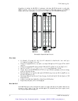
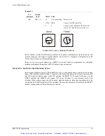
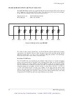
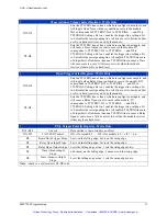
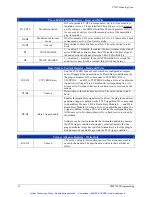
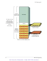
The SMP7500 module contains many user selectable hardware jumpers. The jumpers are of the
2-pin finger removable type found on most personal computers and hard disk drives. These
jumpers set the fly-back protection voltage, the functionality of the front panel (F/P) GND_I/O,
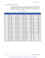
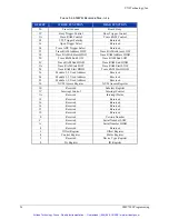
GND_CLK and Global CLK lines, as well as the direction of the PORTs. The Table 2-2 below
shows the appropriate jumper settings for the module setup desired.
Front Panel CLAMP Lines
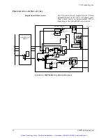
The F/P CLAMP lines are available for user defined voltages that are to be used to suppress
inductive fly-back transients on the PORT lines. This helps protect other circuitry on the PORT’s
data lines from an over-voltage condition. The F/P CLAMP line is only one of several sources that
may be selected to drive the fly-back protection diodes that are installed on the module. Hardware
selectable jumpers on the module can also be used to select 24 V dc, +12 V dc, or
+5 V dc. The voltage selected is routed to the cathode of a fly-back protection diode, whose anode
is then connected to the associated PORT’s data line. Every PORT data line has a fly-back
protection diode installed. If no protection voltage is desired, simply hardware jumper the clamp
voltage to the F/P CLAMP line and do not connect that line to any voltage.
Front Panel GND_I/O Lines
The F/P GND_I/O lines may be configured as either GrouND, or an input line that controls the
direction of the associated PORT. If used as inputs the F/P GND_I/O lines are pulled-up to +5 V
via a 47 k
Ω
resistor. If these lines are configured as input control lines and are not driven low,
they will pull-up setting the associated port as an input. If pulled low, they will set the port to an
output. All F/P GND_I/O lines may be overridden either by a hardware jumper setting or
programmatically to set the port direction to output.
If set to GrouND, these lines can be used as additional user employable Ground pins to the
module. This increases the user attachments to the system’s ground. For high speed switching of
many simultaneous channels it may be necessary to use these pins as ground in order to reduce
signal bounce caused by switching transients. If these lines are used as GND, and they are not
overridden, then they are internally pulled-up and set the PORT’s direction as input.
There are two ways to override the F/P GND_I/O lines. A hardware jumper may be used to select
the PORT as an output, or the PORT may be programmatically set to an output. If these lines are
overridden, then they have no effect on the module.
Front Panel GND_CLK Lines
The F/P GND_CLK lines may be configured as either GrouND, an input line, or an output line
that controls data capture of the associated PORT. If used as inputs the F/P GND_CLK lines are
pulled-up to +5 V via a 47 k
Ω
resistor. There is as well a network of a 120
Ω
resistor in series
with a 100 pF capacitor for termination of the F/P_CLK lines. The polarity of the clock lines are
programmable as well.
If set to GrouND, they can be used as additional user employable Ground pins to the module. This
increases the user attachments to the system’s ground. For high speed switching of many
simultaneous channels it may be necessary to use these pins as ground in order to reduce signal
bounce caused by switching transients.
A Global CLK Line is available on the front panel. This line is to be used to gang several, or all,
PORT clock lines into a single source/destination. The Global CLK line is routed to the required
PORTs via hardware jumpers. If a PORT is configured to use the Global CLK line, then its
associated F/P GND_CLK line has no effect on the module.
Artisan Technology Group - Quality Instrumentation ... Guaranteed | (888) 88-SOURCE | www.artisantg.com


