


APPENDIX F. PowerLink3 IP Communicator,
D-304762 PowerMaster-10/30 G2 Installer's Guide
89
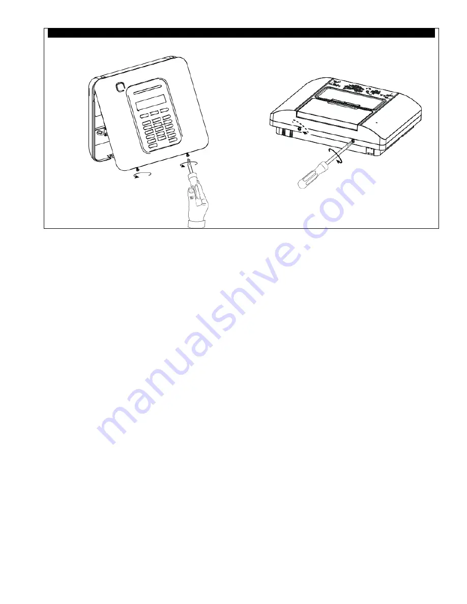
Step 4.
Close the panel and secure with 2 screws:
PowerMaster-10 G2
PowerMaster-30 G2
Control Panel Configuration
The PowerLink3 IP Communicator is integrated with the PowerMaster control panel. This facilitates in the setup of the
required menus that are familiar to the installer.
For detailed programming instructions of the menus, the installer should refer to section 5.6 "Communication".
Setting the Communication Channel
Follow the instructions below to enable DHCP or to set the PowerLink3 IP Communicator IP address.
1. From the PowerMaster control panel, enter "INSTALLER MODE" menu using the Installer Code.
2. Enter the "04:COMMUNICATION" menu.
3. Enter the "7:BROADBAND" menu.
4. Select "Manual IP or "DHCP Client" and set either one.
Note
If "7:BROADBAND" does not appear or if it is not possible to enter the menu, check to make sure that the
PowerLink3 IP Communicator has been correctly installed.
Programming for Configuring Events Reporting to Central Stations
Follow the instructions below to select the type of events to be reported and to determine the method used for reporting
events.
1. From the PowerMaster control panel, enter "INSTALLER MODE" menu using the Installer Code.
2. Enter the "04:COMMUNICATION" menu.
3. Enter the "3:C.S. REPORTING" sub-menu.
4. Program the following menus:
•
"01:REPORT EVENTS" – Select the type of events that the control panel will report to the Central Station.
•
"02:1st RPRT CHAN/03:2nd RPRT CHAN/04:3rd RPRT CHAN" – Define the 1
st
/2
nd
/3
rd
priority of method used
to report events. Select the "broadband" option for PowerLink3 IP Communicator.
•
"21:IP RCVR 1/22:IP RCVR 2" – Enter the Central Station IP address the PowerLink3 IP Communicator will
report to (not mandatory field).


