Disassembly
©2010 Viking Preferred Service
41
To avoid risk of electrical shock, personal injury, or death, disconnect electrical power source to unit, unless test
procedures require power to be connected. Discharge capacitor through a resistor before attempting to service.
Ensure all ground wires are connected before certifying unit as repaired and/or operational.
Back Panel Removal
Condition Requirements:
Island Trim or Backguard Assembly Removed
Note:
VGSC530 shown. Other models will have
different back panels.
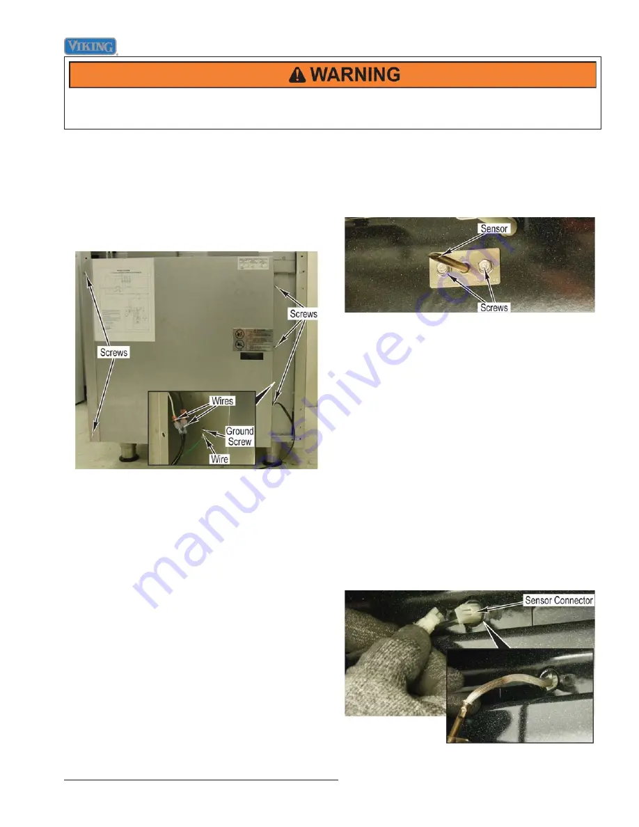
1. Remove screws and back panel from range.
2. Mark and disconnect two wires.
3. Remove ground screw and wire from range.
4. Reverse procedure for installation.
Temperature Sensor (RTD) Removal
(VGSC548 Left Oven)
Condition Requirements:
Door Assembly Removed
1. Remove two screws that attach the sensor to the
back of the oven liner.
2. Pull the sensor from the liner until the sensor
connector protrudes into the oven cavity.
Note:
On some early production models, the opening
in the oven cavity that the RTD attaches had
a smaller diameter, causing the Molex plug
to restrict while pulling the wires forward. The
options would be to either pull the range to
replace the RTD or pull the RTD forward and cut
the two wires and splice in the replacement with
the use of two (2) ceramic wire nut connectors.
3. Apply side pressure to the sensor connector to
secure the connector against the opening in the oven
liner.
4. While maintaining side pressure on the connector,
disconnect the old sensor and connect the new
sensor.
Note:
When installing the oven sensor, it may be
helpful to insert a small screwdriver or awl into
the connector and push the wiring and connector
into place.
5. Install two screws that attach the sensor to the back
of the oven liner.


