Chapter 3 Electrical Installation 21
Liebert EXM 80kVA ~ 200kVA UPS User Manual
1. The cable size of the protective earth cable shall be selected according to the AC power failure level,
cable length and protection type. The grounding wire connection must use the shortest connection route.
2. For the cables with large current, parallel connection of small cables can be adopted to facilitate the
installation.
3. When selecting the battery cable size, the current value in Table 3-1 shall be referred to, and a maximum
voltage drop of 4Vdc is allowed.
4. Do not form coils, so as to minimize the formation of EMI.
3.1.7
Power Cable Connecting Terminal
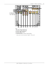
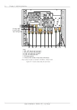
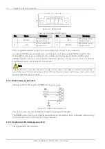
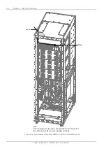
The rectifier input, bypass input, output and battery power cables are connected to the corresponding
terminals shown in Figure 3-2.
3.1.8
Protection Ground
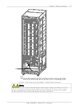
The protective earth cable is reliably connected to the PE input terminal (see Figure 3-2) via the fixing
bolt. All the cabinets and cable troughs shall be grounded according to the local regulations. The
grounding wires shall be tied up reliably to prevent the loosening of the grounding wire tightening screws
when the grounding wires are pulled.
Warning
Failure to ground as required may cause EMI, electric shock or fire risk.
3.1.9
External Protective Device
To ensure the safety, it is necessary to install external circuit breaker for the input and battery of the UPS.
Because of the difference of the specific installations, this section only provides general practical
information for the installation engineer. The qualified installation engineer should have the knowledge of
the local wiring regulations on the equipment to be installed.
Input power supply of rectifier and bypass
1. Input overcurrent and short circuit protection
Install suitable protective devices in the distribution line of the incoming mains supply. The protective
devices should provide functions such as the overcurrent protection, short circuit protection, isolation
protection and tripping upon backfeed. When selecting the protective devices, consider the power cable
current-carrying capacity, system overload capacity (see Table 11-6 and Table 11-7) and the short circuit
capability of the upstream power distribution.
2. Split bypass configuration
If the UPS adopts split bypass configuration, independent protective device shall be installed respectively
on the rectifier input and bypass input distribution lines.
Note
1. The rectifier input and bypass input must use the same neutral line.
2. For IT grid system, 4-pole protective components must be installed for the UPS external input power distribution.
3. Ground fault protection
If the pre-stage input power supply has an RCD, the transient state and steady state ground leakage
current upon the startup of the UPS shall be considered.
Содержание EXM 0080kTK16FN01000
Страница 2: ......
Страница 14: ......
Страница 132: ...118 Chapter 8 Options Liebert EXM 80kVA 200kVA UPS User Manual...
Страница 140: ...126 Chapter 8 Options Liebert EXM 80kVA 200kVA UPS User Manual IS Relay Figure 8 17 Appearance of IS Relay card...


