106 Chapter 7 Parallel System And LBS System
Liebert EXM 80kVA ~ 200kVA UPS User Manual
The following procedures are used to reintegrate a UPS module that has been previously isolated from
the parallel system:
1. Confirm that the I/O cable, battery cable and parallel cable of the single module are correctly connected.
2. Confirm that the maintenance bypass switch Q3 or the single module external maintenance switch is
disconnected. Close the output switch Q5, external output switch, external power bypass switch, bypass
input switch Q2, rectifier input switch Q1, and external power mains switch of each UPS in turn.
3. When the single module starts, close the BCB and then manually turn on the inverter.
After single module inverter starts a few seconds, the single modules form the parallel system for
operation.
7.3.5
Procedures For Completely Powering Down UPS
Complete UPS shutdown and load power-off should follow this procedure. All power switches, isolating
switches and breakers are disconnected, and then UPS no longer supplies power to the load.
Caution
The following procedures will cut off the load power, making the load completely power off.
1. Pressing the EPO button of each UPS stops the operation of rectifier, inverter, static switch and battery.
2. Disconnect the rectifier input switch Q1 and bypass input switch Q2 of each UPS. At the moment, all the
internal power supply is closed and the TOUCHSCREEN does not display any more.
3. Disconnect the output switch Q5 of each UPS.
Warning
1. Post a label at the AC input distribution (generally far away from the UPS) to alert that the UPS maintenance is
being operated.
2. Wait 10 minutes for the internal DC bus capacitance discharging. Then the UPS is completely shut down.
Warning: hazardous battery voltage
The battery terminals still have hazardous voltage after the UPS complete shutdown.
7.3.6
Procedures For Complete UPS Shutdown While Maintaining Power To Load
The following procedures are applicable for completely powering down the UPS and still keeping the
power supply to the load. Refer to the procedures in
7.3.2 Maintenance Bypass Procedures
.
7.4
LBS System
7.4.1
Cabinet Installation
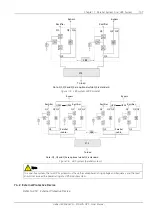
An LBS system consists of two independent UPS systems, each containing one or more parallel UPS
modules, as shown in Figure 7-5 and Figure 7-6. The LBS system has high reliability and is applicable to
the load with multiple inputs. For single-input load, an STS can be installed to feed power to the load.
The system uses the LBS cables to keep the output of the two independent (or parallel) UPS systems in
synchronization. One system is designated as the master, the other is designated as the slave. The
operation modes of the parallel system comprise master and/or slave operation in normal or bypass mode.
Содержание EXM 0080kTK16FN01000
Страница 2: ......
Страница 14: ......
Страница 132: ...118 Chapter 8 Options Liebert EXM 80kVA 200kVA UPS User Manual...
Страница 140: ...126 Chapter 8 Options Liebert EXM 80kVA 200kVA UPS User Manual IS Relay Figure 8 17 Appearance of IS Relay card...

