


The nominal design clearance is 0.02-0.07 mm for the
crankpins and 0.026-0.073 mm for the main bearing journal.
When the running clearance is below the maximum value (0.1
mm for the big-end bearing journals and 0.15 mm for the main
bearing journals), the bearing shells can be re-used.
When the running clearance exceeds the specified maxi-
mum, replace the respective bearing shells with new ones.
Where the crankshaft journals are worn and are reground to
their undersize, change the bearing shells to those oversize.
Thrust washers.
Similar to the bearing shells, no adjust-
ments are possible on the thrust washers. Always renew the
thrust washers when there is scoring, scuffing or flaking.
The thrust washers must be renewed when the crankshaft
endfloat exceeds the specified limit of 0.35 mm. Select new thrust
washers of the standard size or 0.127 mm thicker to have the
endfloat within 0.06 - 0.26 mm.
The crankshaft endfloat is checked with the help of a dial
gauge as outlined in Section «Engine reassembly» (Fig.2-14).
The crankshaft endfloat can be also checked on the engine in
the vehicle. The axial shift of the crankshaft occurs at depressing
and releasing the clutch pedal, the endfloat value is determined
by the front crankshaft end displacement.
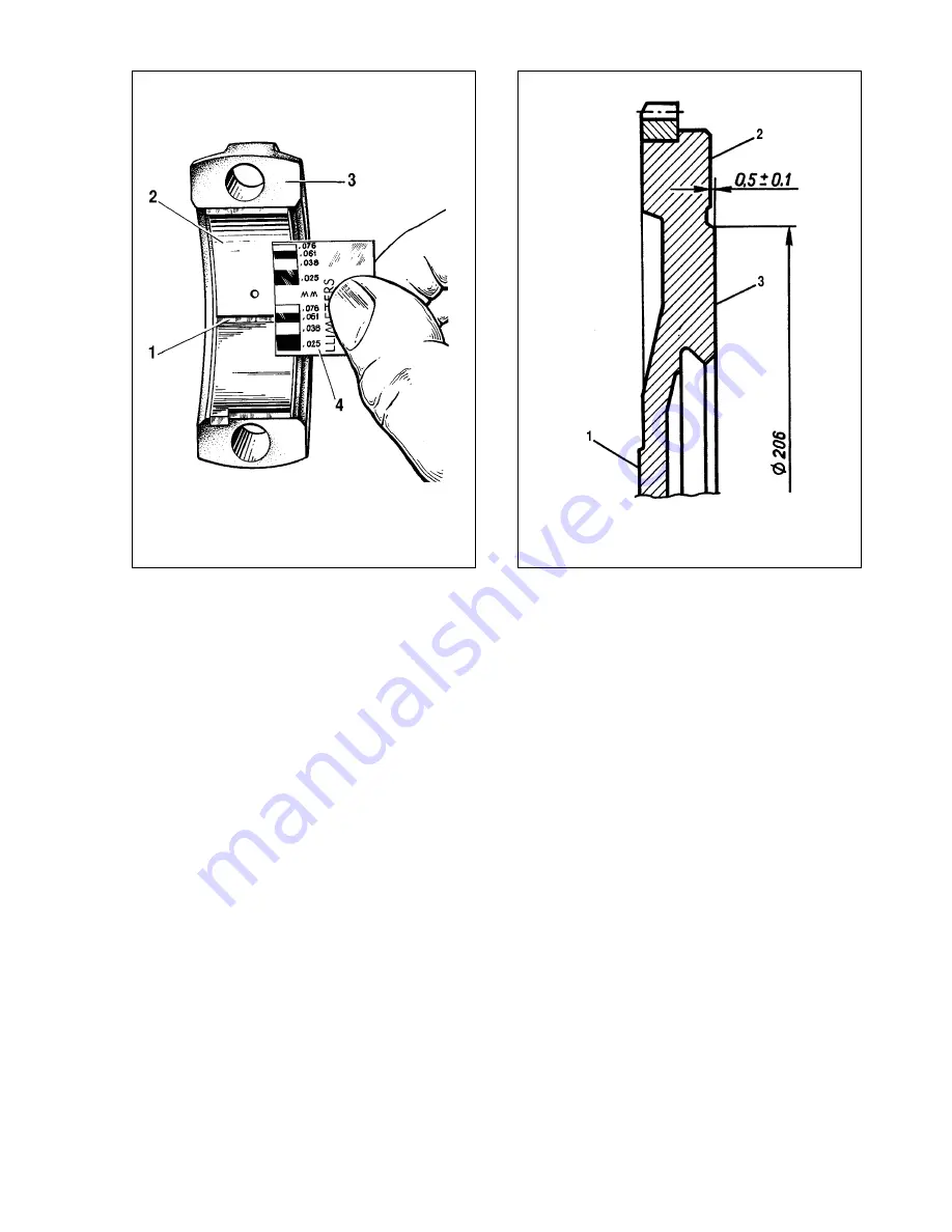
Flywheel.
Inspect the teeth of the flywheel starter ring,
should they are found deteriorated, renew the flywheel. If there
are temper colours on flywheel face 3 (Fig.2-39), check the
starter ring interference on the flywheel. The starter ring should
not rotate when applying 590 ç
•
Ï (60 kgf
•
m).
Check to see there are no scratches or scores on flywheel
face 1 mating the crankshaft flange or on surface 3 mating the
clutch disc.
Remove by lathing all scratches or scores on face 3, provid-
ed the overall thickness is reduced maximum by 1 mm. Do not
forget to lathe surface 2 maintaining the size (0.5±0.1) mm.
Ensure surfaces 2 and 3 are parallel to surface 1. The out-of-par-
allelism tolerance is 0.1 mm.
Mount the flywheel on the tool, centralize is over the mount-
ing bore against surface 1 and check the run-out of surfaces 2
and 3. The run-out values at the outboard points must not exceed
0.1 mm.
Cylinder head and valve gear
General description
Refer to Fig. 2-40 for basic sizes of the valves, guides and
valve seats.
Cylinder head
is an aluminium casting with the pressed-in iron
valve seats and valve guides.
The top of the valve guides is sealed with metal-rubber oil caps
3 (Fig.2-41).
26
Fig.2-38. Measuring the big-end bearing running clearance:
1 - crushed Plastigage; 2 - bearing shell; 3 - big end cap; 4 - scale for clear-
ance measurement
Fig.2-39. Flywheel:
1 - surface mating the crankshaft flange; 2 - surface for clutch securing; 3 -
clutching surface
Содержание 21213
Страница 1: ...VAZ VEHICLES VAZ 21213 VAZ 21214 VAZ 21214 20 VAZ 21215 REPAIR MANUAL ...
Страница 8: ...8 Fig 2 2 Front sectional view of the engine ...
Страница 135: ...135 ...
Страница 136: ...136 ...