


172
Chip off the wing with a sharp thin chisel or cut with a grind-
ing tool over the lines as shown in Fig.8-5.
Detach the wing, remove the remainders of the wing, straight-
en the deformed edges and smooth them with an electric or
pneumatic grinding tool.
Refit the front door and new wing, secure the wing using
quick detachable grips.
Weld the wing in the locations as arrowed in the figure by
means of CO
2
arc welding. Soldering is allowed too. Use solder-
ing bars of ã62, ã63 type (2-3 mm in diameter).
Refit the bonnet and check the wing position. A maximum 2
mm inward or outward misalignment of the wing against the door
or bonnet is allowed; the wing clearances with the bonnet or door
over the outer surface should be (5±2) mm.
Withdraw the bonnet and door.
Use resistance welding with step of 40-50 mm to weld the
wing to the front bodyside panel pillar, splash guard and bulk-
head. Gas welding with tin solder is possible or electric CO
2
arc
welding with a broken seam of 7 to 10 mm with a 50-60 mm step.
Use an electric semi-automatic welder and 0.8 mm dia. wire of
Ò‚.08É1ë or Ò‚.08É2ë type.
Weld the wing to the front by melting the welding flange
edges using a broken seam of 5 to 7 mm with a 40-70 mm step.
Roof - removal
In most cases a damaged roof requires renewal.
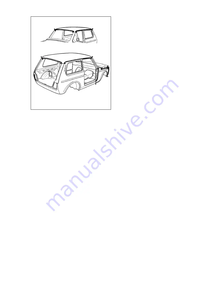
Remove the tailgate, waterchannel trim, windscreen, headlin-
er and roof accessories. Make a layout and cut off the roof panel
over the lines as shown in Fig.8-5.
Detach the roof panel, remove the panel remainder and
straighten any areas deformed. Remove loose colour paint and
base paint up to bare metal on the roof panel edges, windscreen
frame, roof side panels and reinforcements.
Renew the gaskets on reinforcements.
Fit the roof panel, secure it with quick detachable grips, tack
the panel by gas welding in the locations arrowed in Fig.8-5.
Weld the roof panel by resistance welding with a step of 40-
50 mm and by electric CO
2
arc welding or gas welding with a step
of 50-60 mm over the earlier drilled holes of 5-6 mm diameter. To
avoid deformation, start welding from the middle of the seam
rightward and leftward.
Finish the seams with an electric or pneumatic grinding tool.
Paintwork
Polishing
To preserve paintwork and maintain it as long as possible,
select the polishers to suit the condition of the paintwork. Strictly
adhere to recommendations for application.
The basic maintenance routine for the bodywork within the
first two or three months is just regular washing with cold water.
Over further three years move to non-abrasive polishers for new
coatings to restore the brilliance of shine.
After three to five years of vehicle operation, use the auto-
motive polishers intended for weather affected paintwork which
contain a small amount of abrasive. After five years of intensive
use, select the polishers for aged paintwork.
To prevent the polisher drying off, work on small areas buff-
ing them manually with a clean flannel cloth.
To rectify minor paintwork defects, it is recommended to use
polishing pastes of èåÄ-1 or èåÄ-2 type. Hand pads or power
tools, with lambskin discs or flannel discs, can be used for pol-
ishing.
Prior to use, thoroughly mix the paste, dilute it with water
when thick. After polishing, wipe the surface clean with flannel.
Respraying with acrylic paints
Using plenty of water and a putty knife or a brush, rub down
any loose paint from the affected areas.
Use abrasive paper (68ë 8-è or 55ë 4-è) for wet sanding of
the surfaces to be painted. In case of a thin coating and no evi-
dence of mechanical damages, sand the repair area down to the
factory primer layer. In the event of severe corrosion or earlier
applied nitric paints, strip down the areas to the bare metal.
Wash the body with water, blow dry with compressed air.
Degrease the painted surfaces with white spirit or petrol-sol-
vent (Åê-1) and apply bodystopper paste like «Plastisol Ñ-4Ä»
Fig.8-5. Weld Òontours, front wing and roof panel. Dots designate seams
of resistance welding. Arrowed are places tacked by gas welding
Содержание 21213
Страница 1: ...VAZ VEHICLES VAZ 21213 VAZ 21214 VAZ 21214 20 VAZ 21215 REPAIR MANUAL ...
Страница 8: ...8 Fig 2 2 Front sectional view of the engine ...
Страница 135: ...135 ...
Страница 136: ...136 ...