


Make certain the second compression ring is positioned with
the recess facing down (Fig.2-30), while the TOP (or ÇÖêï) mark
should face up (the piston crown).
Before refitting the oil ring, check to see the joint of the coil
expander (spreader ring) is on the side opposite to the ring gap.
Inspection
Scrape away all traces of carbon from the piston and remove
all carbon deposits from the piston/connecting rod oilways.
Thoroughly examine the components. Make sure there are
no cracks of any sort on the piston, piston rings, gudgeon pin,
connecting rod or big-end cap. Renew the bearing shell if there
is obvious scoring or scuffing.
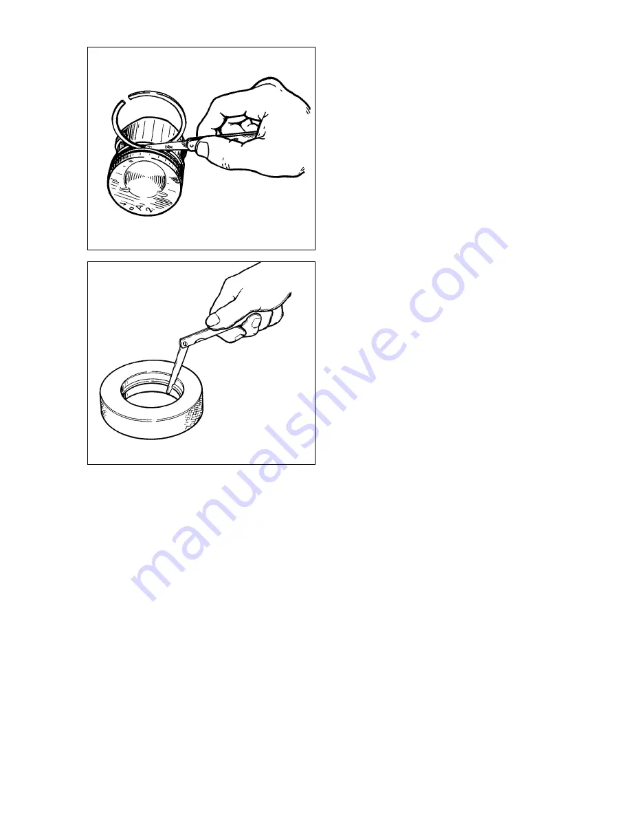
The piston-ring-to-groove wall clearance is checked using
feeler blades as shown in Fig.2-34, fitting the ring into the respec-
tive groove. For new components the design clearance (rounded
off to the nearest 0.01 mm) is 0.04-0.07 mm for the first com-
pression ring; 0.03-0.06 mm for the second compression ring and
0.02-0.05 mm for the oil control ring. When worn, the tolerance
must not exceed the specified maximum of 0.15 mm.
The piston ring gap should be checked with a feeler gauge
via inserting the rings into the gauge (Fig.2-35), with the bore
equal to the piston ring nominal diameter ±0.003 mm. Use gauge
67.8125.9502 for the normal 82 mm rings.
The gap for all new piston rings should be within 0.25 to 0.45
mm. The maximum permitted gap for worn rings is 1 mm.
Crankshaft and flywheel
Design description
Basic dimensions of the crankshaft are shown in Fig.2-36.
Crankshaft
is cast-iron, of five bearings. The crankshaft
journals can be reground during the engine overhaul when the
diameter is reduced by 0.25 mm, 0.5 mm, 0.75 mm and 1mm.
The crankshaft endfloat is restricted by two thrust washers.
The thrust washers are fitted on both sides of the rear main bear-
ing: a sintered one (yellow) at the rear end and a steel-aluminium
one at the front end. The thrust washers are of two sizes - stan-
dard and 0.127 mm thicker.
Crankshaft bearing shells
are thin-walled, aluminium with
steel backing. The upper bearing shells of No 1, 2, 4 Ë 5 bearings
have inner oil grooves, whilst the lower bearing shells are plain
shells. The upper and lower bearing shells of the centre bearing
(No 3) are plain, without an oil groove. The big-end bearing shells
(both upper and lower ones) are also plain.
The oversize bearing shells are thicker for the crankshaft
journals reduced by 0.25 mm, 0.5 mm, 0.75 mm and 1 mm.
Flywheel
is cast iron with the pressed-in steel starter ring.
The flywheel centering is ensured by a front input shaft bearing
which is pressed into the crankshaft.
A taper recess on the rear face of the flywheel near the ring
gear is provided as a positioning mark. Adjust it against cylinder
No 4 crankpin.
Inspection and overhaul
Crankshaft.
Inspect the crankshaft. Make sure there are no
cracks. Examine the faces which mate the oil seal working edges
for evident cracking, scoring or scuffing.
Mount the crankshaft on two V-blocks as shown in Fig.2-37
and check the run-out with a dial gauge:
•
main bearing journals - maximum 0.03 mm;
•
mounting surfaces for the input shaft sprocket and bearing
- maximum 0.04 mm;
•
surface mating the oil seal - maximum 0.05 mm.
Measure the diameters of the main bearing journals and
24
Fig.2-34. Checking the piston ring-to-groove gap
Fig. 2-35. Checking the piston ring gap
Содержание 21213
Страница 1: ...VAZ VEHICLES VAZ 21213 VAZ 21214 VAZ 21214 20 VAZ 21215 REPAIR MANUAL ...
Страница 8: ...8 Fig 2 2 Front sectional view of the engine ...
Страница 135: ...135 ...
Страница 136: ...136 ...