


crankpins. Regrind when the wear is in excess of 0.03 mm, oval-
ity is over 0.03 mm, or when scoring and scuffing is obvious.
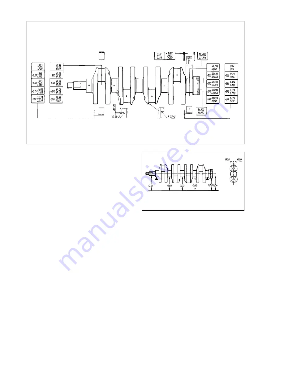
Regrind the journals and crankpins through reducing the
diameter to the nearest undersize (Fig.2-36).
When regrinding, observe the sizes for the crankshaft fillet as
shown in Fig.2-36 for the standard-size crankshaft.
The ovality and taper for the main bearing journals and big-
end bearing journals after regrinding must not exceed 0.005 mm.
On a reground crankshaft, the vertical offset of the crankpins
axes must be 0.35 mm (Fig.2-37). To check this, place the crank-
shaft on V-blocks and position the crankshaft so that No1
crankpin axis is in the horizontal plane passing through the main
bearing journal axes. Using a dial gauge, check the vertical off-
set of crankpins No 2, No 3 and No 4 against crankpin No 1.
After regrinding the journals and crankpins, polish them using
the diamond paste or special grinding pastes.
After regrinding and followed finishing, unplug the oilways,
then machine the plug seats with the mill-cutter Ä.94016/10 and
spindle Ä.94016. Thoroughly wash the crankshaft and oilways to
flush abrasive residuals and blow dry with compressed air.
Use tool Ä.86010 to press in new plugs and punch each plug
in three points with a centre-punch.
On crankshaft web No 1 mark the reduced amount (under-
size) of the main bearing journals and big-end journals (eg. M
0.25; B 0.50).
Bearing shells.
Remember that no adjustment on the bear-
ing shells is allowed. Renew the shells when there are scratches,
scoring or flaking.
The main and big-end bearing running clearance is checked
by measuring the components. It is convenient to check the
clearance with the help of «Plastigage» (which consists of a fine
thread of perfectly-round plastic, which is compressed between
the bearing cap shell and the crankshaft journal) under the fol-
lowing procedure:
- ensure the journals and bearing shells are clean and dry,
cut several pieces of the appropriate-size Plastigage (they should
be slightly shorter than the width of the bearings) and place one
piece on each crankshaft journal axis;
- with the bearing shells in position in the cages, fit the caps to
their original locations (depending on the journal checked). Take care
not to disturb the Plastigage. Then tighten the securing nuts and bolts
to the specified torque. Tighten the connecting rod bolts to 51 ç
•
Ï
(5.2 kgf•m), while the main bearing cap bolts to 80.4 ç
•
Ï (8.2 kgf
•
m);
- remove the bearing cap and check the running clearance by
comparing the width of the crushed Plastigage on each journal
with the scale printed on the card gauge to obtain the bearing
running clearance (Fig.2-38).
25
Fig.2-36. Basic crankshaft dimensions
Fig.2-37. Permissible runouts for basic crankshaft surfaces
Содержание 21213
Страница 1: ...VAZ VEHICLES VAZ 21213 VAZ 21214 VAZ 21214 20 VAZ 21215 REPAIR MANUAL ...
Страница 8: ...8 Fig 2 2 Front sectional view of the engine ...
Страница 135: ...135 ...
Страница 136: ...136 ...