


192
Check the injection system for satisfactory operation, as out-
lined in Repair Manual for Fuel Sequential Injection System.
Engine - dismantling and reassembly
The main differences on dismantling and reassembly are
related to alternative design of the air supply system.
Mount the engine on the test bench, drain oil from the oil pan,
dismantle the engine in the order described below.
Disconnect supply 1/return 3 coolant hoses (Fig.9-8) and idle
crankcase vent hose from throttle manifold 2. Undo the nuts hold-
ing the throttle housing to receiver unit 12 and withdraw the throt-
tle housing with gasket 13.
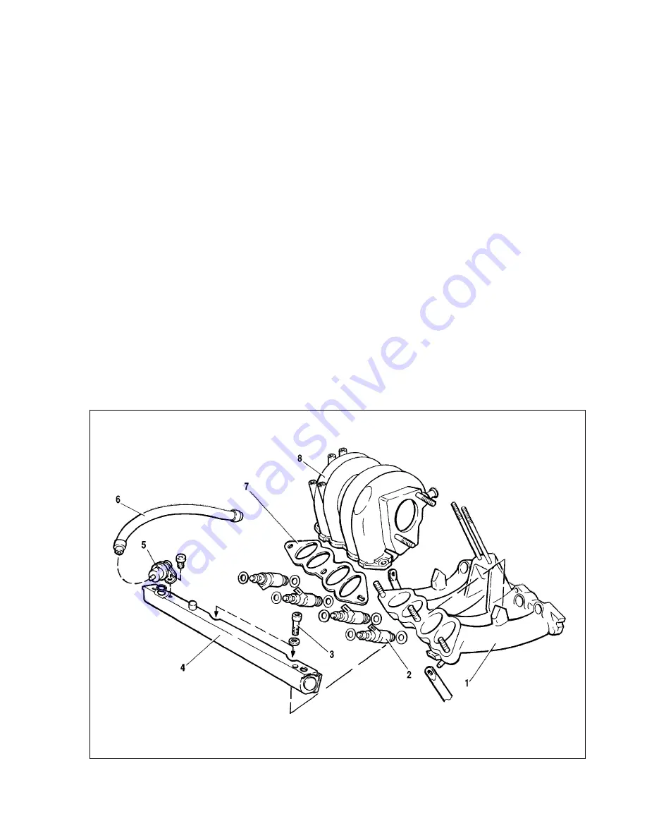
Disconnect and remove supply 9 /return 1 fuel pipes (Fig.9-6)
from fuel rail 10, fuel pressure regulator and from the bracket on
the receiver unit. Detach and remove vacuum hose 6 (Fig.9-9)
from receiver unit 8 and fuel pressure regulator 5.
Undo five nuts holding the receiver unit to intake pipe 1 and
withdraw the receiver unit complete with gasket 7.
Disconnect the wiring from the injectors, withdraw fuel rail 4
with pressure regulator 5, having undone two bolts 3 holding it to
the intake pipe. Undo retaining nuts and bolts, withdraw the
brackets, followed by the intake pipe with the shield. Detach the
ignition module and knock sensor from the left-hand side of the
engine.
Further engine dismantling is as described in chapter 2 of this
Manual. The engine reassembly is reverse of the dismantling pro-
cedure. Before refitting the fuel rail, lubricate the injector sealing
rings with motor oil.
Valve mechanism - design description
Valves 2 (Fig.9-10) are operated by the cams through rocker
arms 3. One end of the lever presses down the valve, while the
other end rests on the spherical head of the hydraulic lifter. The
hydraulic lifters automatically eliminate the clearance in the valve
train, so during technical service you do not need to check or
adjust the valve clearances.
Lubricating oil through pipe 3 (Fig.9-11) flows to the tensioner
cavity «E» (Fig. 9-12), through the bore «Ñ» and valve unit 2 into
the working cavity «Ç» pushing down plunger 5. Tensioner hous-
ing 1 has a 1 mm bore to release air in the cavity «Ö».
The diameter clearance between housing 1 and plunger 5
should be 0.018-0.024 mm and is measured as a difference
between the maximum measured diameter of plunger 5 and min-
imum measured diameter of housing 1.
The tensioner housing and plunger make a unit, where no
replacement of either part is allowed once the clearance has
been selected. Plunger 5 should easily stroke within housing 1 up
to 16 mm.
Fig.9-9. Removing the fuel system components:
1 - intake manifold; 2 - injector; 3 - bolt; 4 - fuel fail; 5 - fuel pressure regulator; 6 - vacuum hose; 7 - gasket; 8 - receiver unit
Содержание 21213
Страница 1: ...VAZ VEHICLES VAZ 21213 VAZ 21214 VAZ 21214 20 VAZ 21215 REPAIR MANUAL ...
Страница 8: ...8 Fig 2 2 Front sectional view of the engine ...
Страница 135: ...135 ...
Страница 136: ...136 ...