


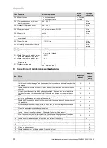


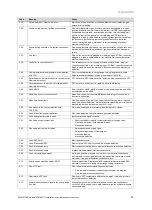
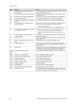


10 Troubleshooting
42
Installation and maintenance instructions auroCOMPACT 0020181589_04
Applicability:
Austria
Danger!
Risk of poisoning due to increased CO
values.
An incorrect gas restrictor size can lead to
increased CO values.
▶
When replacing the Venturi, ensure
that you use the correct gas restrictor
(colour coding and position of pins on
the underside of the gas restrictor).
Caution.
Risk of material damage to the product.
Lubricant can block function-related chan-
nels in the Venturi.
▶
Do not use lubricant when installing the
gas restrictor.
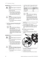
▶
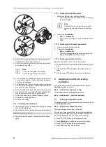
Insert the gas restrictor for the type of gas in question
into the new Venturi (yellow: G20 natural gas, grey:
G31 liquid gas).
Note
Make sure that the colour of the gas re-
strictor matches the colour of the coding
resistor on the PCB.
When inserting the gas restrictor, ensure
that the gas restrictor is correctly aligned
using the indicated position marks on the
upper side of the Venturi and also the posi-
tioning pins
(5)
on the underside of the gas
restrictor.
Applicability:
Germany
Danger!
Risk of poisoning due to increased CO
values.
An incorrect gas restrictor size can lead to
increased CO values.
▶
When replacing the Venturi, ensure
that you use the correct gas restrictor
(colour coding and position of pins on
the underside of the gas restrictor).
Caution.
Risk of material damage to the product.
Lubricant can block function-related chan-
nels in the Venturi.
▶
Do not use lubricant when installing the
gas restrictor.
▶
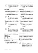
Insert the gas restrictor for the gas group in question
(which may have been replaced) into the (new) Ven-
turi.
Type of gas
Colour of the gas
restrictor
G20 natural gas
Yellow
G25 natural gas
Blue
G31 propane
Grey
Note
Make sure that the colour of the gas re-
strictor matches the colour of the coding
resistor on the PCB.
When inserting the gas restrictor, ensure
that the gas restrictor is correctly aligned
using the indicated position marks on the
upper side of the Venturi and also the posi-
tioning pins
(5)
on the underside of the gas
restrictor.
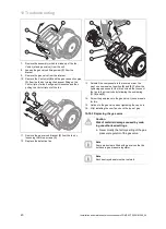
8.
Reinstall the components in the reverse order. Use new
seals for this.
9.
After installing the new Venturi jet, check the type of
gas and set the gas ratio (
→
Page 20).
10. If you cannot adjust the CO2 content, the gas restrictor
has been damaged during installation. In this case,
replace the gas restrictor with an appropriate spare
part.
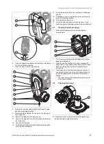
10.10.5 Replacing the heat exchanger
1.
Empty the product
2.
Remove the compact thermal module. (
→
Page 34)
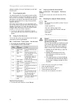
3.
Detach the condensate drain hose from the heat ex-
changer.
1
1
2
3
4.
Remove the clamps
(2)
and
(3)
from the flow connec-
tion and the return connection.
5.
Detach the flow connection.
6.
Detach the return connection.
7.
Remove two screws
(1)
on each of the two retainers.


