


5 Installation
18
Installation and maintenance instructions auroCOMPACT 0020181589_04
1.
If you install the product in protective area 2, it must be
operated as room-sealed. Installation method B53P is
not permitted in this case.
2.
Open the electronics box.
3.
The mains connection cable selected must meet the
requirements of the protective area.
4.
Carry out the wiring.
5.
Close the electronics box.
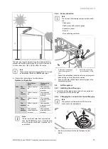
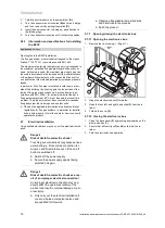
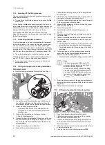
5.7.5
Connecting the solar sensor
1
1.
To install the solar sensor, follow the installation instruc-
tions for the solar collector.
2.
Route the cable for the solar sensor
(1)
from the col-
lector to the product's solar plug.
1
2
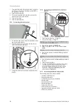
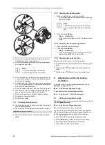
3.
Connect the cable for the solar sensor
(1)
to the solar
plug
(2)
.
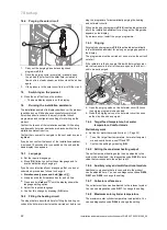
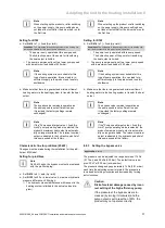
5.7.6
Connecting controllers to the electronic
system
– +
24V=
RT BUS
Burner
off
1.
Open the electronics box. (
→
Page 16)
2.
Carry out the wiring. (
→
Page 17)
Conditions
: If you are connecting a weather-controlled
eBUS
controller or
a room-temperature-controlled
eBUS
controller:
▶
Connect the controller to the
BUS
plug.
▶
Bridge the plug
24 V = RT
if it has not been bridged
already.
Conditions
: If you are connecting a low-voltage controller (24 V):
▶
Connect the controller to the
24 V = RT
plug instead of
the bridge.
Conditions
: If you are connecting a safety thermostat for underfloor heat-
ing:
▶
Connect the thermostat to the
Burner off
plug instead of
the shunt.
3.
Close the electronics box.
4.
To trigger the
Comfort
pump operating mode (pump
runs permanently) using a multi-circuit controller,
change the diagnostics code D.018 Pump operat-
ing mode (
→
Page 29) from
Eco (3)
(pump runs
intermittently) to
Comfort (1)
.
5.7.7
Connecting additional components
The following components can be actuated:
–
Hot water circulation pump
–
External heating pump
–
Cylinder charging pump (not activated)
–
Extractor hood
–
External solenoid valve
–
External fault signal
–
Solar pump (not active)
–
eBUS remote control (not active)
–
Legionella protection pump (not active)
–
Solar valve (not active).


