Troubleshooting 10
0020181589_04 auroCOMPACT Installation and maintenance instructions
39
10.3
Reading off the fault codes
If a fault develops in the product, the display shows a fault
code
F.xx
.
Fault codes have priority over all other displays.
If multiple faults occur at the same time, the display shows
the corresponding fault codes for two seconds each in se-
quence.
▶
Rectify the fault.
▶
To restart the product, press the fault clearance key (
Operating instructions).
▶
If you are unable to remedy the fault and the fault recurs
despite several fault clearance attempts, contact Vaillant
Customer Service.
10.4
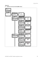
Querying the fault memory
Menu
→
Installer level Fault list
The product has a fault memory. You can use this to query
the last ten faults that occurred in chronological order.
The display shows:
–
The number of faults that have occurred
–
The fault currently selected with fault number
F.xx
–
A plain text display explaining the fault.
▶
Use the
or
button to display the last ten faults that
occurred.
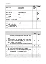
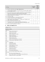
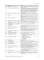
Overview of fault codes (
→
Page 52)
10.5
Resetting the fault memory
▶
To delete the entire fault list, press
(
Delete
,
OK
)
twice.
10.6
Performing diagnostics
▶
You can use the function menu (
→
Page 34) to actuate
and test individual components of the product during the
fault diagnostics.
10.7
Using check programmes
You can also use check programmes for troubleshooting.
10.8
Resetting parameters to factory settings
▶
To reset all parameters simultaneously to the default
settings, set
D.096
to
1
.
10.9
Preparing the repair work
1.
Decommission the product.
2.
Disconnect the product from the power mains.
3.
Remove the front casing.
4.
Close the gas isolator cock.
5.
Close the service valves in the heating flow and in the
heating return.
6.
Close the service valve in the cold water pipe.
7.
Drain the product if you want to replace water-bearing
components of the product.
8.
Make sure that water does not drip on live components
(e.g. the electronics box).
9.
Use only new seals.
10.10 Replacing defective components
10.10.1 Replacing the burner
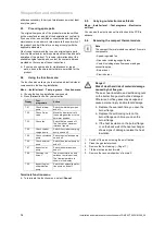
1.
Remove the compact thermal module. (
→
Page 34)
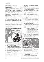
1
2.
Undo the four screws on the burner
(1)
.
3.
Remove the burner.
4.
Fit the new burner with a new seal.
5.
Ensure that the recesses on the seal and burner are
aligned with the sight glass on the burner door.
6.
Install the compact thermal module. (
→
Page 36)
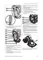
10.10.2 Replacing the fan
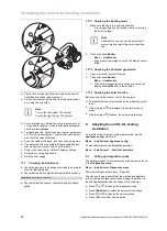
1
3
2
8
4
7
5
6
1.
Remove the air intake pipe.
2.
Remove the three plugs
(1)
and
(6)
from the gas valve.
3.
Remove the plug from the sensor on the Venturi jet
(4)
by pressing on the locking lug.
4.
Remove the plug(s) (depending on the unit version)
(8)
from the fan motor by pressing on the locking lug.
5.
Undo the two cap nuts
(5)
and
(7)
on the gas valve.
Hold on to the gas valve when loosening the cap nuts.
6.
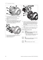
Undo the three screws
(3)
between the mixer tube
(2)
and the fan flange.


