Installation 5
0020181589_04 auroCOMPACT Installation and maintenance instructions
15
H
L1
L2
L3
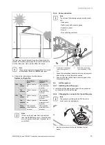
The total pipe length between the solar collectors and the
cylinder must not be greater than 20 m in the inflow and 20
m in the return.
(L)
=
(L1)
+
(L2)
+
(L3)
= 40 m max.
Note
These values apply for a height
(H)
of 12,5 m and
an installation that has a
(DN 16)
solar pipe.
▶
Observe the information in the table below.
System configuration
Solar flat col-
lector
Vacuum solar
collector
150L
One
sensor
Without accessor-
ies
With expansion
vessel and/or buf-
fer vessel
Two
sensors
Without accessor-
ies
With expansion
vessel and/or buf-
fer vessel
190L
One
sensor
Without accessor-
ies
With expansion
vessel and/or buf-
fer vessel
Two
sensors
Without accessor-
ies
With expansion
vessel and/or buf-
fer vessel
Three
sensors
With expansion
vessel and/or buf-
fer vessel
With expansion
vessel and/or buf-
fer vessel
Note
If there is a lack of solar fluid in the installa-
tions, fault
F.1355
may occur. Check the pres-
sure in the solar circuit and, if required, top it
up with fluid.
5.5.4
Solar connection
Note
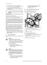
The unit has the following components as stand-
ard:
- Solar pump
- Safety group with pressure gauge
- Expansion vessel
- Air vent
- Brine collecting container
2
1
1
Solar return connection
(from the collector), G
3/4
2
Solar flow connection
(to the collector), G 3/4
1.
Consult the installation instructions for the solar system
when setting up the hydraulic connection.
2.
Connect the solar circuit's flow and return pipes to the
floor-standing boiler.
5.6
Air/flue system
5.6.1
Installing the air/flue pipe
▶
Install the air/flue pipe as described in the separate set-
up instructions for the air/flue pipe.
5.6.2
Changing the connector for the air/flue pipe
Note
The products are fitted with a 60/100 mm dia-
meter connector as standard.
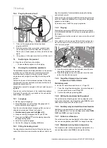
A
B
C
1.
Insert a screwdriver into the slot between the test
points.

