Operation
,
Display
and
Application
Examples
VDF650
User
Manual
-
64
-
4
.
8
.
5
Pulse
Setting
as
the
Frequency
Source
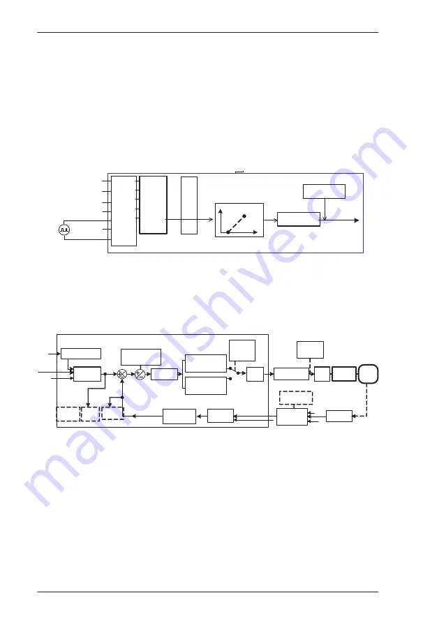
In
many
scenarios
,
pulse
input
is
used
as
the
frequency
source
.
The
specifcations
of
pulse
signals
are
:
voltage
9
–
30
V
,
frequency
0
–
100
kHz
.
Only
DI5
can be
used
for pulse
input
.
The relationship between
pulse
input
from DI5
and
the
corresponding
setting
is
set
in
P4
-
28
to
P4
-
31
.
The
relationship
is
a
two
-
point
line
,
and
100
%
of
pulse
input
corresponding
setting
corresponds
to
the
maximum
frequency
of
P0
-
10
,
as
shown
in
Figure
4
-
22
.
Figure
4
-
22
Pulse
setting
as
the
frequency
source
P4
-
00
P4
-
01
P4
-
02
P4
-
03
P4
-
04
.
.
.
.
.
30
.
P0
-
03
=
5
Running
frequency
Terminal
Function
code
Setting
value
DI1
DI2
DI3
DI4
DI5
.
COM
Frequency
source
selection
OC
output
P0
-
07
=
0
Pulse setting
Frequency
feature setting
P4
-
28 to P4
-
31
:
Relationship between
pulse setting frequency
and running frequency
*
Only
DI5
can be used for pulse input
.
4
.
8
.
6
Frequency
Closed
-
Loop
Control
The VDF650 has a built
-
in PID regulator
.
Together with the frequency sources
,
the PID
regulator can implement automatic adjustment of progress control
,
such as constant
temperature
,
constant
pressure
,
and
tension
control
.
Figure
4
-
23
Automatic
adjustment
by
PID
regulator
P0
-
07
=
0
P0
-
27
=
0
P0
-
03
=
8
Frequency
source selection
PA
-
00
(
PID
setting
source
)
Setting
target
Built
-
in
PID
regulator
PA
-
01
(
PID
digital setting
)
PA
-
03
(
PID
action
direction
)
0
:
Forward
action
1
:
Reverse action
PA
-
09
(
PID
deviation
limit
)
FA
-
04
(
PID
setting
feedback
range
)
PID 1
:
Proportional Kp 1
:
PA
-
05
Integral Ti1
:
PA
-
06
Derivative Td1
:
PA
-
07
PID 2
:
Proportional Kp 2
:
PA
-
15
Integral Ti2
:
PA
-
16
Derivative Td2
:
PA
-
17
PA
-
13
PA
-
23
PA
-
24
PWM
drive
Execution
by
motor
Object
PA
-
18
PA
-
19
PA
-
20
Switchover
condition
Transmitter
detection
PA
-
12
(
PID
feedback
filter time
)
PA
-
02
(
PID
feedback
source
)
PID
feedback
PID
output
feature
PID
output
frequency
U0
-
15
(
PID
setting
)
U0
-
16
(
PID
feedback
)
PID
setting
P4
-
33
AI parameter
feature
preprocessing
P4
-
13 to P 4
-
32
(
Calibration
curve
)
Physical
quantity
Electric
signal
%
%
%
When
PID
frequency
closed
-
loop
control
is
implemented
,
P0
-
03
(
Main
frequency
source
X
selection
)
must
be
set
to
8
(
PID
).
The
PID
-
related
parameters
are
set
in
group
PA
,
as
shown
in
Figure
4
-
23
.
The VDF650 has two built
-
in equivalent PID calculating units
.
You can set the features
,
such
as adjustment
speed
and
accuracy
,
for the two units
separately
based
on the actual
conditions
.
Switchover between the two units can be implemented automatically or by
means
of
an
external
DI
terminal
.
Содержание VDF650 Series
Страница 1: ...VDF650 Series High Performance AC Drive...
Страница 9: ......
Страница 10: ...1 Safety Information and Precautions...
Страница 17: ...Safety Information and Precautions VDF650 User Manual 16...
Страница 18: ...2 Product Information...
Страница 29: ...Product Information VDF650 User Manual 28...
Страница 30: ...3 Mechanical and Electrical Installation...
Страница 46: ...4 Operation Display and Application Examples...
Страница 79: ...Operation Display and Application Examples VDF650 User Manual 78...
Страница 80: ...5 Function Code Table...
Страница 136: ...6 Description of Function Codes...
Страница 248: ...7 EMC...
Страница 260: ...8 Selection and Dimensions...
Страница 285: ...Selection and Dimensions VDF650 User Manual 284...
Страница 286: ...9 Maintenance and Troubleshooting...


