Documents are only to be used and distributed completely and unchanged, especially including the section ”Safety information”. This is page 15 of a document consisting of
49 pages. The instructions for use describe only the actual product. If the product is older or newer than the date of writing, it is strictly the users´ responsibility to check carefully
the validity of the document (if in doubt, order appropriate instructions for use). 99 90 34 / 12/09/2003
The exhaust waste vapour condenser enables an efficient con-
densation of the pumped vapours at the outlet.
☞
Next to 100% solvent recovery.
☞
The cover protects against glass splinters in the event of
breaking, acts as thermal isolation to avoid the condensa-
tion of humidity and is intended to absorb shocks.
☞
Install hoses for cooling water at the inlet and outlet (hose
nozzle 6 mm), check hose connection.
➨
Ensure that the system design does not allow the coolant
outlet pipeline to become blocked.
☞
Ensure that the system design does not allow the exhaust
pipeline to be blocked (hose nozzle 10 mm), do not permit
uncontrolled pressurizing.
☞
Connect the exhaust to a suitable treatment plant to pre-
vent the discharge of dangerous gases and vapours to the
surrounding atmosphere.
Before operation MZ 2C VARIO / MD 4C VARIO:
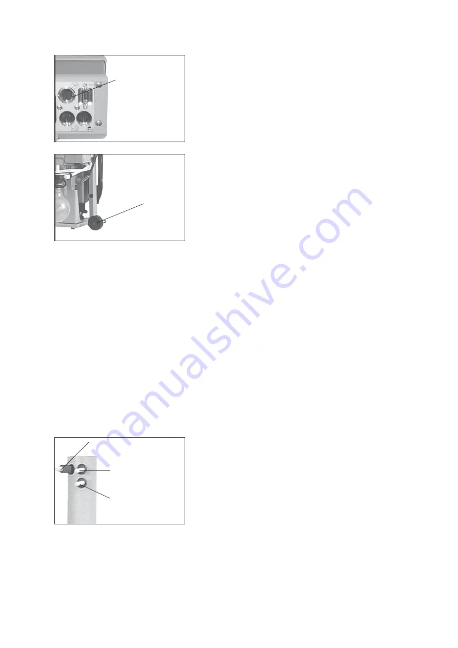
Connect cable from the frequency converter of the pump to the controller (rear side): trip line and power
supply of the frequency converter.
coolant outlet
(hose nozzle 6 mm)
coolant inlet
(hose nozzle 6 mm)
outlet
(gas!; hose nozzle 10 mm)
Connect the cable of the gauge head to the female connector
at the rear side of the vacuum controller.
Connect the gauge head to the vacuum system by using a
small flange connection or a hose connection.
☞
The device is adjusted together with the gauge head at the
factory. If the gauge head is replaced a readjustment is rec-
ommended.
➨
Connect cable from the frequency converter of the pump to
the controller (rear side): trip line and power supply of the
frequency converter.
female connector
to connect gauge
head
VSK 5
Max. permitted pressure at the pressure transducer: 2 bar (ab-
solute).
☞
The display flashes at a pressure higher than 1100 mbar.
☞
Obey max. permitted pressure.
☞
Inside a vacuum system where evaporation occurs, e. g.
rotary evaporator, the vacuum is not uniform, e. g. a con-
denser acts as pump or the vacuum in the pipeline is lower
than in the system. Therefore carefully choose position
where to connect the gauge head.
☞
Condensate and deposits in the pressure transducer affect the measuring result.
☞
In case of deposits, aggressive or condensable media, install a gas washing bottle before the pressure
transducer if necessary.
☞
In order to avoid malfunction it is important to position the pressure transducer in the vacuum line so as
to avoid flow of condensate towards the pressure transducer.
☞
Clean pressure transducer if necessary, see section “maintenance“.
☞
Preselections at the controller, see section “
Modes“.
☞
Use and operation of the controller see section
“How to operate the controller”.
☞
Setting of interface parameters, see section
“Interface“.
gauge
head
VSK 5
Before operation PC 2002 VARIO / PC 2003 VARIO / PC 2004 VARIO:


