background image

17

Part Replacement Continued

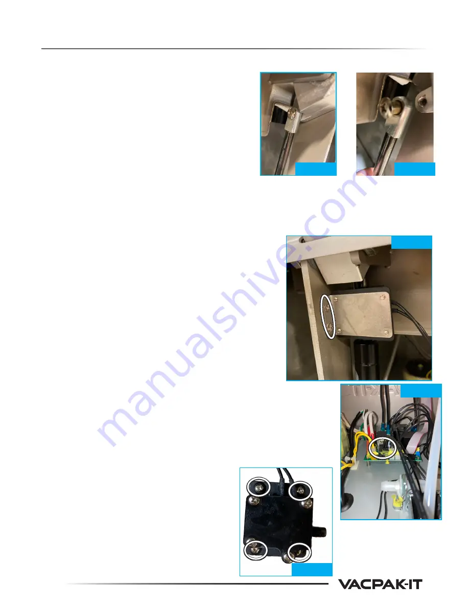
5.  Remove Phillips head screw from upper Lid 

Strut mounting tab (Fig. 27)

6.  Remove Lid Strut from upper mounting post 

(Fig. 28)

7.  Installation is reverse of removal steps

Fig. 27

Fig. 28

Time Estimate: Approximately 10 minutes

Testing: Ensure mounting bracket is not bent or damaged


   Good = Continuity between wires when toggle 

pin is depressed


   Bad = No continuity between wires when toggle 

pin is depressed, replace

Part: #186PMICRSW2

1.  Follow pre-maintenance steps on page 10

2.  Remove Phillips head screws from the rear panel of 

the machine


Note: 11 screws on 186VMC16F, 8 screws on 

186VMC20F and 186VMC20FGF

3.  Remove 2 Phillips head screws from microswitch 

mounting plate (Fig. 29)

4.  Disconnect wire plug from main circuit board (Fig. 30)

5.  Remove 4 Phillips head screws from

mounting plate and remove microswitch (Fig. 31)

6.  Installation is reverse of removal steps

Lid Microswitch

Fig. 29

Fig. 30

Fig. 31

Содержание 186VMC16F

Страница 1: ... perform the procedure REVISED 07 2021 NOTICE 186VMC16F 2 16 Seal Bars Floor Model Chamber V acuum Sealer 186VMC20F 2 20 Seal Bars 186VMC20FGF 2 20 Seal Bars with Gas Flush NOTICE This manual is for a certified service technician and should not be used by those who are not porperly trained This manual cannot cover all possible conditions that may occur and is not intended to be all encompassing Yo...

Страница 2: ...atch Assembly 12 Pressure Gauge 13 Front Circuit Board 13 Piston 14 Power Switch 15 Vacuum Pump 15 Lid Strut 16 Lid Microswitch 17 Transformer 18 Main Circuit Board 18 Small Solenoid Valve 19 Small Control Solenoid Valve 20 Large Control Solenoid Valve 20 Drain and Inlet Solenoid Valve 21 Wire Diagram for VMC16F 22 Wire Diagram for VMC20F 23 Wire Diagram for VMC20FGF 24 ...

Страница 3: ...a brief description of the issue Including clear pictures of the issue will help expedite the process Failure to include one or more of these items will extend the processing time Serial Plates Ready Kitchen W arranty Note All units are labeled with model numbers Voltage Wattage Serial Number Item number and Certifications on the rear of the unit Please do not remove this label 序列号按订单数量排序 下一单流水号接着...

Страница 4: ...Remove oil port cap with an 8mm hex key Fig 2 B 7 Use oil filler container to fill pump via oil port fill pump up to half way between minimum and maximum lines Fig 2 C Note Oil level will fluctuate during initial filling ensure level holds before moving on 8 Replace oil port cap and oil fill window 9 Attach the supplied power cord to the rear of the machine Fig 3 Fig 1 A B A A A A C Fig 3 Fig 2 A ...

Страница 5: ...UP or DOWN arrow buttons to adjust as needed Fig 4 B Note Vacuum Cycle is adjustable from 0 90 seconds 5 second intervals Gas Cycle is adjustable from 0 10 seconds 0 5 second intervals Sealing Cycle is adjustable from 0 6 seconds 0 5 second intervals Cooling Cycle is adjustable from 0 10 seconds 0 5 second intervals 5 After setting all the cycle times press the SET button again to exit the setup m...

Страница 6: ...ur product is placed into the pouch ensure there is at least a 2 gap between the product and the pouch opening Note Remember to protect sharp items from puncturing the pouch 7 Lay the pouch flat in the vacuum chamber and lay the opening flat across the sealing bar Ensure there are no wrinkles in the pouch across the sealing bar and that the pouch end is not out side the chamber 7a If you have a ga...

Страница 7: ...to remove any food or any other debris Recommended mild soap part 999SUNBRIGHT 3 Wipe the outside of the machine as needed with appropriate stainless steel cleaner to remove any food or debris Recommended stainless steel cleaner part 148EXCEL 4 Inspect power cord for any damage and replace if damaged 5 Ensure pump oil level is at required level using the pump site gauge Recommended oil part 186OIL...

Страница 8: ...ge fluid level 4 Adjust vacuum cycle time 5 Check lid 11 Check lid sealing gasket 11 Check voltage is getting to the pump 15 Check solenoid valve 19 Check main circuit board 18 Front circuit board does not come on Ensure correct power is supplied Ensure unit is plugged in Check to see if fuse is blown 10 Check switch for voltage and function 15 Check front circuit board 13 E01 error is showing Ens...

Страница 9: ...9 Check control solenoid valve 21 Check piston 14 Check silicone tubing Check circuit board 18 Pump starts while lid is still open Check microswitch 17 Check circuit board 18 LP error is showing Check fuse 10 Check power cord Check transformer 18 CLO error is showing Check silicone tubing for leaks Check control solenoid valve 19 Check solenoid valve 20 Check circuit board 18 ...

Страница 10: ...mate Approximately 5 minutes Part 186PFUSE1 1 Follow pre maintenance steps 2 Open fuse holder box by gently pushing a flat screwdriver into the side opening Fig 10 3 Remove fuse and replace as needed Fuse Fig 9 Fig 10 Fig 8 Pre Maintenance 1 Turn off the unit Fig 8 2 Unplug power cord from power supply 3 Ensure lid is open ...

Страница 11: ... sec tions replace if any are found 3 Remove sealing foam from lid by pulling it out of the mount channel on the lid Fig 12 Part 186PSEALPAD2 186VMC16F ONLY 186P20FTOPBA 186VMC20F 186VMC20FGF 4 Remove sealing foam mount channel by removing 1 Phillips head screw from the middle of the mount Fig 13 Lid Sealing Gasket Visually inspect cracks or damage replace if any are found 5 Remove lid sealing gas...

Страница 12: ...20F ONLY 186P20FGFSB 186VMC20FGF ONLY 1 Follow pre maintenance steps from page 10 2 Lift sealing bar up from mounting tabs Fig 13 3 Reverse steps to install Sealing Bar Fig 13 Fig 12 Time Estimate Approximately 20 minutes Part 186PLID20 1 Follow pre maintenance steps from page 10 2 Remove Phillips head screws from rear panel Note 11 screws on 186VMC16F 8 screws on 186VMC20F and 186VMC20FGF 3 Remov...

Страница 13: ...th a 8mm socket Fig 15 B 5 Pull Pressure Gauge from mounting bar and out the front of the Control Panel 6 Installation is reverse of the removal steps Pressure Gauge Time Estimate Approximately 20 minutes Testing Good Red wire in ribbon has voltage Bad Red wire in ribbon no voltage Visual Test Check board for black or burn marks scratches or cracks Part 186P20F17 1 Follow pre maintenance steps fro...

Страница 14: ...ing replace Part 186PPISTON 1 Follow pre maintenance steps on page 10 2 Remove Phillips head screws from rear panel Note 11 screws on 186VMC16F 8 screws on 186VMC20F and 186VMC20FGF 3 Remove wire and ring terminal from stud post on bottom of piston Fig 17 4 Remove vacuum hose from side of piston housing under vacuum chamber Fig 18 5 Remove hex bolt from top of piston inside vacuum chamber with a 1...

Страница 15: ...e 4 Phillips head screws from mounting bracket and remove power switch Fig 23 5 Installation is reverse of removal steps Power Switch Fig 21 Fig 22 Fig 23 Time Estimate Approximately 60 minutes Testing Check power is getting to pump Oil is milky white color replace oil and check for leaking vacuum hoses or excess moisture in vacuum chamber or product Replace if pump not creating vacuum Part 186PPU...

Страница 16: ... Strut mount ing tab with a 7mm socket Fig 26 4 Remove Lid Strut from lower mounting post by pulling away from mount arm Continued on page 17 Lid Strut 4 Remove 3 hex nuts with a 14mm socket from under the machine for the mounting post legs for the pump Fig 24 5 Disconnect the power wires going to the Main Circuit board Fig 25 B 6 Remove Phillips head screw that is securing the ground wire termina...

Страница 17: ...epressed Bad No continuity between wires when toggle pin is depressed replace Part 186PMICRSW2 1 Follow pre maintenance steps on page 10 2 Remove Phillips head screws from the rear panel of the machine Note 11 screws on 186VMC16F 8 screws on 186VMC20F and 186VMC20FGF 3 Remove 2 Phillips head screws from microswitch mounting plate Fig 29 4 Disconnect wire plug from main circuit board Fig 30 5 Remov...

Страница 18: ... the machine Note 11 screws on 186VMC16F 8 screws on 186VMC20F and 186VMC20FGF 3 Remove hex nut from top of transformer with a 13mm socket Fig 32 A 4 Disconnect wires from main circuit board and note wire locations Fig 32 B 5 Installation is reverse of removal steps Transformer Time Estimate Approximately 45 minutes Testing Visually look for burn or black marks check for cracks or breaks in board ...

Страница 19: ...FGF 3 Disconnect wires from main circuit board and note location Fig 33 4 Remove Phillips screw from plastic clamp holding tubing and valve down Fig 34 5 Remove poly tubing from either side of the valve by pulling them away from the center of the valve Fig 35 6 Installation is reverse of removal steps Small Solenoid Valve Fig 33 Fig 34 Fig 35 3 Remove wires connected to the main circuit board note...

Страница 20: ...ns 4 Remove Phillips head screw from plastic hose clamp Fig 36 5 Remove hoses by pulling off of barb fittings on valve Fig 37 6 Installation is reverse of removal steps Small Control Solenoid Valve Fig 36 Time Estimate Approximately 20 minutes Testing Good Continuity between wires 43 0 Ohms of resistance Bad No continuity between wires Part 186P20F54 1 Follow pre maintenance steps on page 10 2 Rem...

Страница 21: ...isconnect wires from Main Circuit Board and note location 5 Remove from mounting bracket by pushing the valve forward Fig 39 6 Remove hose by pulling off the barb fitting on the valve Fig 40 7 Installation is reverse of removal steps Drain and Inlet Solenoid Valve 3 Remove wires connected to the main circuit board note locations 4 Remove 2 Phillips head screws from the under side of the metal tray...

Страница 22: ...22 Wire Diagram for VMC16F ...

Страница 23: ...23 Wire Diagram for VMC20F ...

Страница 24: ...24 Wire Diagram for VMC20FGF ...

Страница 25: ...86PLID20 20 Power switch 186PSWITCH 25 Caster wheel with brake 186P20F31 26 Caster wheel no brake 186P20F32 29 Vacuum pump 186P20F35 35 Transformer 186P16F 43 Lid gasket 186PGASKET3 45 Chamber lid 186P16FLID 46 Lid hinge 186PHINGE 50 Lid strut 186PSTRUT2 53 Solenoid valve drain 54 Solenoid valve inlet 57 Solenoid valve piston 186P16FSV 58 Main control circuit board 186PRELAY 61 Lid microswitch 186...

Страница 26: ...it board 186P20F17 20 Lid lock assembly 186PLID20 24 Power switch 186PSWITCH 31 Caster wheel with brake 186P20F31 32 Caster wheel no brake 186P20F32 35 Vacuum pump 186P20F35 41 Transformer 186P20F41 43 Main circuit board 186PRELAY 44 Microswitch 186PMICRSW2 47 Solenoid valve piston 186P16FSV 54 Solenoid valve inlet drain 186P20F54 56 Lid hinge 186PHINGE 58 Lid strut 186P20F58 62 Lid gasket 186PGAS...

Страница 27: ...6P20F17 22 Lid lock assembly 186PLID20 26 Power switch 186PSWITCH 33 Caster wheel with brake 186P20F31 34 Caster wheel no brake 186P20F32 37 Vacuum pump 186P20F35 43 Transformer 186P20F41 45 Main circuit board 186PRELAY 46 Microswitch 186PMICRSW2 49 Solenoid valve gas fill 52 Solenoid valve piston 186P16FSV 59 Solenoid valve inlet drain 186P20F54 61 Lid hinge 186PHINGE 63 Lid strut 186P20F58 67 Li...

Отзывы: