


24
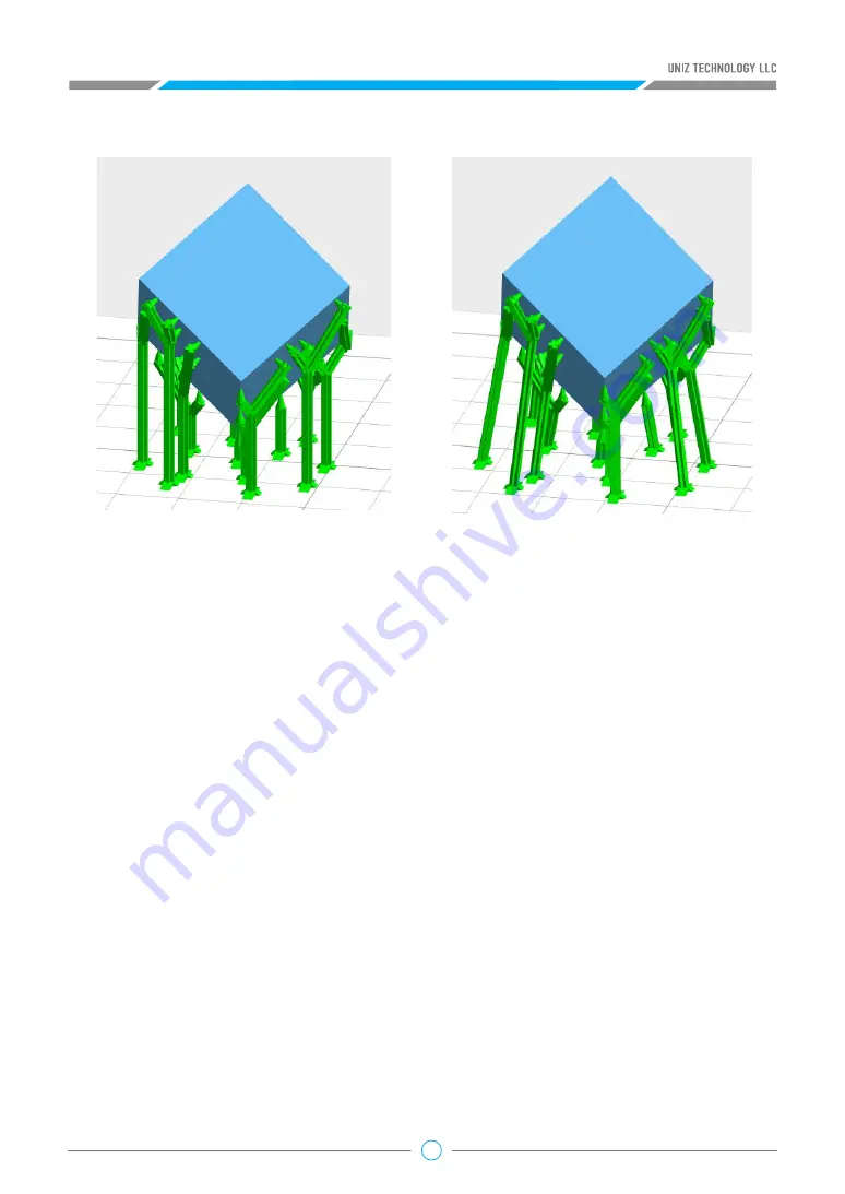
The left picture below is vertical supports and the right is with tilted supports.
Press the “Edit” button, the system enters manual edit support mode. Even if the object is not
selected, you can edit supports manually. Click the “Edit” button again, the system will return to
automatic support mode.
Trace the mouse cursor over the model, when your cursor appears as a green line, clicking on the
surface of the model will add a support. If the cursor appears as a red line, it means a support is
not needed.
Click on the surface of the support and, it will be highlighted to indicate that it has been selected.
Once selected, you can drag and drop the support to a target location. If the support turns red
while moving, the position of the support is not ideal and therefore it is not recommended.
You can also change the Support Radius, Header Length, or Point Size sliders to modify support
properties.
Once a support is selected simply press the “DELETE” key to remove it.
Add Support
Modify Support
Delete Support
• “Lift”: lift the activated object from the build platform upwards by 5mm.
• “Down”: push the activated object down to the build platform.
• “Generate”: generate the support structure using the current settings for all selected models.
• “Edit”: allow the user to manually add, modify, or delete support structures.
• Entry/Exit Manual Edit


