11
2
INSTALLATION AND CONNECTION
11
INSTALLAT
ION AND CONNECTION
Chapter
2
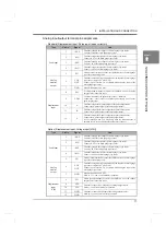
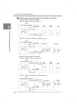
Analog input/output terminal pin assignments
- Standard (Displacement input: Pulse input (open collector))
- Option (Displacement input: Voltage input [VIN])
Type
Pin No.
Signal
Use
Load input
1
+EXC
Terminal to supply the voltage of the strain gauge type sensor.
CIN of the strain gauge type sensor.
2
-SIG
Terminal to input the signal of the strain gauge type sensor.
Connect –OUT of the strain gauge type sensor.
3
-EXC
Terminal to supply the voltage of the strain gauge type sensor.
Connect -IN of the strain gauge type sensor.
4
+SIG
Terminal to input the signal of the strain gauge type sensor.
COUT of the strain gauge type sensor.
5
F.G.
Frame ground terminal to connect the shielded wire of the strain gauge
type sensor connecting cable.
Analog
monitor
output
6
VOL
OUT
Terminal to output voltage proportional to the input of the strain gauge
type sensor. (Approx. 2V per 1mV/V)
Connect a pen recorder, etc., for simply monitoring the input of the
strain gauge type sensor.
7
GND
Ground terminal of VOL OUT.
Displacement
input
8
F.G.
Frame ground terminal to connect the shielded wire of the pulse
output sensor connecting cable.
9
COM
Common terminal of the pulse output sensor. (+common)
Connect the + side (+24) of the external power supply (24V) for the
pulse output sensor.
10
A
Terminal to input the A-phase output of the pulse output sensor.
Connect the A-phase output of the pulse output sensor.
11
B
Terminal to input the B-phase output of the pulse output sensor.
Connect the A-phase output of the pulse output sensor.
12
Z
Terminal to input the Z-phase output of the pulse output sensor.
Connect the A-phase output of the pulse output sensor.
It is not usually wired. It is wired only when the indicated value is
adjusted to zero at the original point of the rotary encoder.
Type
Pin No.
Signal
Use
Load input
1
+EXC
Terminal to supply the voltage of the strain gauge type sensor.
CIN of the strain gauge type sensor.
2
-SIG
Terminal to input the signal of the strain gauge type sensor.
Connect –OUT of the strain gauge type sensor.
3
-EXC
Terminal to supply the voltage of the strain gauge type sensor.
Connect -IN of the strain gauge type sensor.
4
+SIG
Terminal to input the signal of the strain gauge type sensor.
COUT of the strain gauge type sensor.
5
F.G.
Frame ground terminal to connect the shielded wire of the strain gauge
type sensor connecting cable.
Analog
monitor
output
6
VOL
OUT
Terminal to output voltage proportional to the input of the strain gauge
type sensor. (Approx. 2V per 1mV/V)
Connect a pen recorder, etc., for simply monitoring the input of the
strain gauge type sensor.
7
GND
Ground terminal of VOL OUT.
Pin Nos. 7, 11, and 12 are internally connected.
Displacement
input
(VIN)
8
F.G.
Frame ground terminal to connect the shielded wire of the voltage
output sensor connecting cable.
9
VIN
Terminal to connect the +output of the voltage output sensor.
Pin Nos. 9 and 10 are internally connected.
10
VIN
11
GND
Terminal to connect the -output of the voltage output sensor.
Pin Nos. 7,11 and 12 are internally connected.
12
GND
Содержание DeviceNet F381A
Страница 1: ...15APR2013REV 3 10 DYNAMIC FORCE PROCESSOR F381A OPERATION MANUAL ...
Страница 9: ...Contents VIII Contents VIII M E M O ...
Страница 34: ...25 2 INSTALLATION AND CONNECTION 25 INSTALLATION AND CONNECTION Chapter 2 M E M O ...
Страница 147: ...138 8 SPECIFICATIONS 138 SPECIFICATIONS Chapter 8 8 2 Outside dimensions Unit mm ...
Страница 164: ......

