17
2
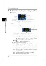
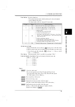
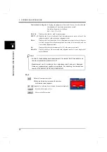
INSTALLATION AND CONNECTION
17
INSTALLAT
ION AND CONNECTION
Chapter
2
■
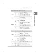
Connector pin assignments
* Input COM and Input COM, Output COM and Output COM are internally connected.
* Input COM and Output COM are internally isolated.
* Input COM and F.G., Output COM and F.G. are connected with the capacitor.
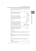
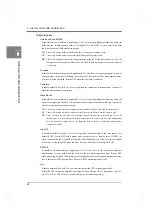
[1] There is a judgment (NG judgment) which all of the judgment outputs LO, OK and HI are not
set to on.Please fetch the outputs in synchronization with the Complete output is changed from
OFF
→
ON.
(
See Page 21 "- Input signal timing check"
[2] Please confirm turning OFF and ON(OFF
→
ON) of the Complete output at every
measurement to confirm the measurement has been updated.
A1
IN
Load Digital Zero
B1
IN
Work 1
A2
IN
DPM Positioning
B2
IN
Work 2
A3
IN
Start
B3
IN
Work 4
A4
IN
Stop
B4
IN
Work 8
A5
IN
Hold
B5
IN
N.C
A6
IN
Reset
B6
IN
N.C
A7
IN
Backlight On
B7
IN
N.C
A8
IN
Prohibit Touch Panel
B8
IN
N.C
A9
IN
COM
(Input)
Plus common connection: +24V
Minus common connection: 0V
B9
IN
COM
(Input)
Plus common connection: +24V
Minus common connection: 0V
A10
IN
COM
(Input)
Plus common connection: +24V
Minus common connection: 0V
B10
IN
COM
(Input)
Plus common connection: +24V
Minus common connection: 0V
A11
OUT
COM
(Output)
Sink type (Standard): 0V
Source type (ISC): +24V
B11
OUT
COM
(Output)
Sink type (Standard): 0V
Source type (ISC): +24V
A12 OUT
COM
(Output)
Sink type (Standard): 0V
Source type (ISC): +24V
B12
OUT
COM
(Output)
Sink type (Standard): 0V
Source type (ISC): +24V
A13 OUT
Hold
Result
Load
LO
[1]
B13
OUT
Wave Result
LO
[1]
A14 OUT
OK
[1]
B14
OUT
OK
[1]
A15 OUT
HI
[1]
B15
OUT
HI
[1]
A16 OUT
DPM
LO
[1]
B16
OUT Complete
[1][2]
A17 OUT
OK
[1]
B17
OUT Run
A18 OUT
HI
[1]
B18
OUT Load OK
A19 OUT Overload
B19
OUT DPM OK
A20 OUT N.C
B20
OUT SD OK
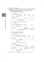
Connect elements that can pass Ic=5mA or more.
The leak current of the elements connected should be 400
μ
A or less.
Attention
A1
B1
A20
B20
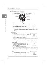
The adaptable connector
Connector: FCN-361J040-AU (attachments)
Cover: FCN-360C040-B (attachments)
Содержание DeviceNet F381A
Страница 1: ...15APR2013REV 3 10 DYNAMIC FORCE PROCESSOR F381A OPERATION MANUAL ...
Страница 9: ...Contents VIII Contents VIII M E M O ...
Страница 34: ...25 2 INSTALLATION AND CONNECTION 25 INSTALLATION AND CONNECTION Chapter 2 M E M O ...
Страница 147: ...138 8 SPECIFICATIONS 138 SPECIFICATIONS Chapter 8 8 2 Outside dimensions Unit mm ...
Страница 164: ......


