


40
4
SETTINGS AND CALIBRATIONS
40
SE
TTINGS
A
ND CAL
IB
R
ATIONS
Chapter
4
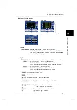
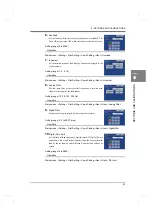
1.
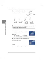
Excitation Voltage
Select an excitation voltage.
* If the excitation voltage is changed, perform re-calibration.
Operation
Setting range (2.5, 10V)
Main screen
→
Setting
→
First Setting
→
Y-axis Setting
→
Exc. Voltage
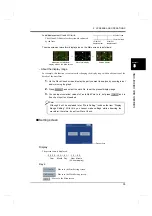
2.
Unit
Select a unit.
Operation
Setting range (See "9-3.Unit setting list"on p.147.)
Main screen
→
Setting
→
First Setting
→
Y-axis Setting
→
Unit
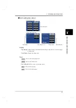
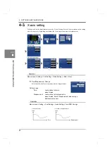
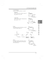
3.
Zero Calibration
Register the present sensor input as zero.
Press
with the load sensor unloaded.
Operation
Setting range (-3.333 to 3.333 mV/V)
Main screen
→
Setting
→
First Setting
→
Y-axis Setting
→
Zero Cal.
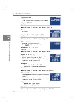
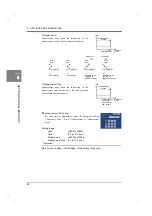
4.
Equivalent Input Calibration
Input the rated output and rated capacity (display value)
described on the data sheet of the load sensor.
Also, set the decimal place here. Input the decimal point
together when inputting the display value.
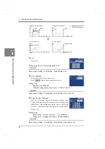
Setting range
Rated output
(-9.999 to 9.999 mV/V)
Operation
Display value (rated capacity) (-9999 to 9999)
Main screen
→
Setting
→
First Setting
→
Y-axis Setting
→
Next
→
Equiv. Cal.
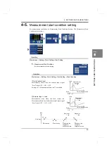
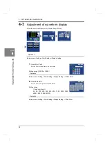
5.
Actual Load Calibration
Apply actual load to the load sensor, and input the load value at
that time.
Also, set the decimal place here. Input the decimal point
together when inputting the calibration value.
Setting range
Calibration value (-9999 to 9999)
Operation
Display value
(display only)
Main screen
→
Setting
→
First Setting
→
Y-axis Setting
→
Next
→
Actual Cal.
Содержание DeviceNet F381A
Страница 1: ...15APR2013REV 3 10 DYNAMIC FORCE PROCESSOR F381A OPERATION MANUAL ...
Страница 9: ...Contents VIII Contents VIII M E M O ...
Страница 34: ...25 2 INSTALLATION AND CONNECTION 25 INSTALLATION AND CONNECTION Chapter 2 M E M O ...
Страница 147: ...138 8 SPECIFICATIONS 138 SPECIFICATIONS Chapter 8 8 2 Outside dimensions Unit mm ...
Страница 164: ......