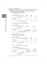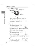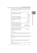
4
1
OUTLINE
4
OUTLINE
Chapter
1
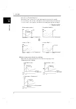
respectively, as “Waveform Reference.”
Normally use “Front,” but use “Back” if the displacement for insertion work is applied.
* In case of “Front”, the waveform of which 0mm is the measurement start point is displayed.
In case of “Back”, the waveform of which 0mm is the measurement stop point is displayed.
●
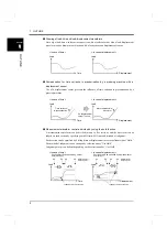
Various measurement start and stop conditions
Measurement start and stop conditions can be selected according to application.
- Measurement Start Condition
<
Measurement waveform >
Displacement
Load
<
Comparison waveform >
Displacement
Load
<
In case of “Front” >
Displacement
Load
<
In case of “Back” >
Displacement
Load
Front
Back
Measurement
Front
Back
Same back
Same front
0mm
0mm
Measurement waveform
Comparison waveform
waveform
5mm
-5mm
0mm 5mm
10mm
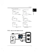
< Only External Input >
< External Input + Load >
< External Input + Displacement >
Start
OFF
ON
Load
Section
Load
Start
OFF
ON
Start
load
Load
Displacement
Start
OFF
ON
Start
displacement
Time or
displacement
Time or
displacement
Measurement
Section
Measurement
Section
Measurement
Содержание DeviceNet F381A
Страница 1: ...15APR2013REV 3 10 DYNAMIC FORCE PROCESSOR F381A OPERATION MANUAL ...
Страница 9: ...Contents VIII Contents VIII M E M O ...
Страница 34: ...25 2 INSTALLATION AND CONNECTION 25 INSTALLATION AND CONNECTION Chapter 2 M E M O ...
Страница 147: ...138 8 SPECIFICATIONS 138 SPECIFICATIONS Chapter 8 8 2 Outside dimensions Unit mm ...
Страница 164: ......


