background image

User’s Manual                                                                                                                                                                                                MSO/UPO2000 Seri es 


  93 / 137


Instruments.uni-trend.com 


master and slave computer. The bus is a multiple master bus that prevents data corruption through conflict 
detection and arbitration mechanisms. It is worth noting that the I

2

C bus has two address bit widths, 7 bits 

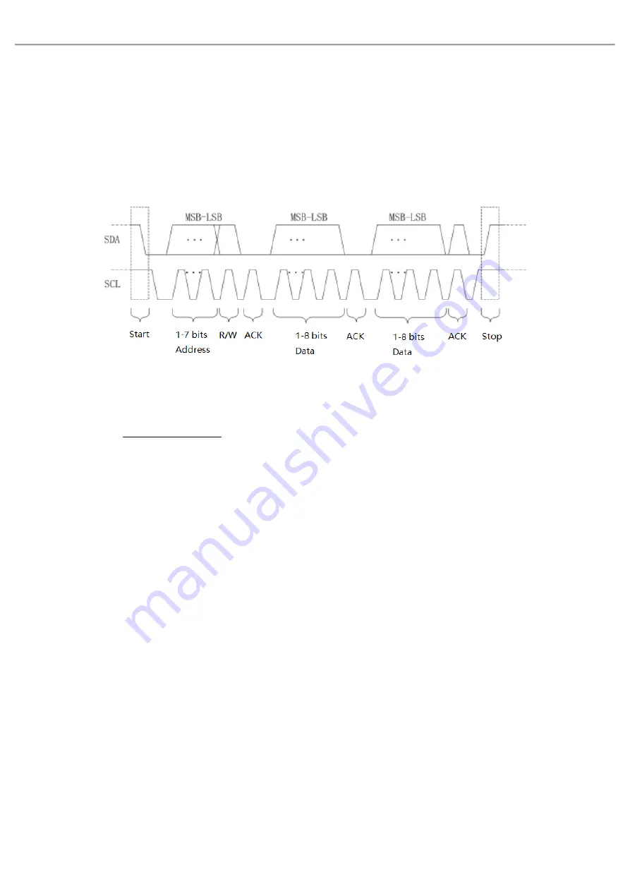
and 10 bits, where 10 bits and 7 bits addresses are compatible that can be used in combination. When the bus 
is idle, both lines are high level. When any device on the bus output low level, it will make the bus signal goes 
low, i.e., the signals of multiple devices are " wired and" logic. This special logic relation is the key to bus 
arbitration. The protocol requires that the data SDA must remain stable while the clock line SCL is high, and 
the data is usually transmitted in MSB form. As shown in Figure 14-2. 


Figure 14-2 

(1)


Bus Decoding 
Refer to

 RS232 Bus Decoding. 

(2)


SCL SOURCE 
Select SCL source to any one of CH1

CH4 or D0-D15 to be clock input of I

2

C. 

(3)


SDA Source 
Select SDA source to any one of CH1

CH4 or D0-D15 to be data input of I

2

C.   


14.3    SPI Decoding 

        SPI  (serial  peripheral  interface)  can  connect  the  host  with  peripheral  equipment  in  serial  way  to 

communication. It’s full duplex and synchronous communication bus. It’s usually use 4 signal connecting 
line, MOSI: master data output, slave data input; MISO: master input, slave data output; SCLK: clock 
signal generated by master; CS: chip select enable signal from slave. 


SPI  interface  is  mainly  used  for  synchronous  serial  data  transfer  between  the  host  and  low-speed 
peripheral equipment. Under the shift pulse of the host, the data is transferred bit by bit, the high bit in 
front and behind is the low bit. SPI interface is widely used because it does not require slave address 
addressing, which is full duplex communication and the protocol is simple. SPI protocol transmission as 
shown in Figure 14-3. 

Содержание UPO2102

Страница 1: ...User s Manual MSO UPO2000 Series Digital Phosphor Oscilloscope...

Страница 2: ...Technology China Co Ltd All rights reserved Trademark Information UNI T is the registered trademark of Uni Trend Technology China Co Ltd Document Version MSO UPO200020220624 V1 00 Statement UNI T pro...

Страница 3: ...If the product is shipped domestically to the location of the UNI T service center UNI T shall pay the return shipping fee If the product is sent to any other location the customer shall be responsib...

Страница 4: ...herwise specified in the product manual Safety Statement Warning Warning indicates the presence of a hazard It reminds users to pay attention to a certain operation process operation method or similar...

Страница 5: ...lar equipment such as electronic instruments and electronic equipment electronic equipment with protective measures and any high voltage and low voltage circuits such as the copier in the office CAT I...

Страница 6: ...avoid fire and impact of excessive current Please consult the product manual for detailed rated values before connection Use the power cord properly You can only use the special power cord for the ins...

Страница 7: ...d dry environment with ambient temperature from 0 to 40 Do not use this device in explosive dusty or humid air Do not operate in humid environment Do not use this device in a humid environment to avoi...

Страница 8: ...n of AC power supply that can input Voltage Range Frequency 100 240VAC Fluctuations 10 50 60Hz Please use the attached power lead to connect to the power port Connecting to service cable This instrume...

Страница 9: ...lloscope that is easy to use with excellent technical specifications a perfect combination of many functionalities that can help users to quickly complete testing MSO UPO2000 series is aimed at satisf...

Страница 10: ...ltiple channels independent trigger fluorescent display Multiple channels with independent hardware 7 digits frequency meter DVM supports multiple channels independent AC DC TRMS true virtual value me...

Страница 11: ...Guide This chapter introduces on using the oscilloscope for the first time the front and rear panels the user interface as well as the built in help system General Inspection Before Use Front Panel Re...

Страница 12: ...distributors UNI T will arrange maintenance or replacement 4 2 Before Use To perform a quick verification of the instrument s normal operations please follow the steps below 1 Connect to the Power Sup...

Страница 13: ...on the probe to 10x and connect the probe to CH1 Make sure the probe s connector is properly connected with theoscilloscope Connect the probe s main clip and ground clip to the oscilloscope s compensa...

Страница 14: ...key 10 Clear all control key 11 Compensating signal connector and ground terminal 12 Factory setting LA 16 digital channel AWG function arbitrary waveform generator protocol decoding Print Screen key...

Страница 15: ...240 V 50 60Hz 7 Power Switch Turn on power switch after AC socket is connect properly the oscilloscope can be power on normally Press power supply soft key on the front panel to boot the oscilloscope...

Страница 16: ...e channel moves to left or right Horizontal position parameter will display on the top of the screen in real time Press this knob to return the channel display back to the midpoint position Horizontal...

Страница 17: ...n orange 7 Clear All Press this key to clear all the recalled waveform on the screen If the oscilloscope is in RUN state then keep refresh new waveform 8 PrintScreen Press this key to save waveform as...

Страница 18: ...ay setting menu It can set waveform display type grid type grid brightness waveform brightness background brightness duration color temperature anti color temperature pop up window transparency and de...

Страница 19: ...ate press this key to playback waveform press it again to pause playback Record Press this key to start recording waveform 14 HOME Menu Tap HOME icon to pop out HOME shortcut menu list as show in Figu...

Страница 20: ...age depth of the current scale 4 Waveform indicator 5 Waveform trigger position Display the trigger position of the current waveform 6 Horizontal displacement Display the horizontal displacement value...

Страница 21: ...al scale Display vertical scale of CH1 when CH1 is activated This parameter can be changed by using SCALE knob on vertical control area d Probe attenuationfactor Display probe attenuationfactor of CH1...

Страница 22: ...state ON or OFF b Source Set the measuring source of multimeter which can set to CH1 CH2 CH3 or CH4 c Mode AC DC AC DC 12 Help Tap help icon in HOME menu to enter help menu 13 Analog channel icon and...

Страница 23: ...gure 4 9 Squeeze Gesture 3 Drag Use one finger to press and drag the selected item to the aimed position as shown in Figure 4 10 Drag gesture can use for Drag waveform to change waveform displacement...

Страница 24: ...perating waveform mode is opened Operating waveform mode of the oscilloscope is enabled by default 5 Touch shortcut operating Separate two fingers and meanwhile slide two fingers to one direction this...

Страница 25: ...ral options This symbol represents that there has next menu This symbol represents that the menu has two options This symbol represents that multipurpose knob and jog dial on the front panel can be us...

Страница 26: ...annel 4 analog channels are CH1 CH4 Vertical channel setting method of each channel is quite the same 2 analog channels are CH1 CH2 In this chapter take 1 channel 1 as example to introduce vertical ch...

Страница 27: ...Channel Coupling Set channel coupling mode in channel which can select to DC direct current AC alternating current and ground DC AC Ground 5 3 Bandwidth Limitation The bandwidth limit can set to 20 MH...

Страница 28: ...se Set the reverse phase in channel When reverse phase is turned on the voltage value of waveform will be reversed and the reverse icon will display on the screen as shown in Figure 5 2 Figure 5 1 Rev...

Страница 29: ...User s Manual MSO UPO2000 Series 29 137 Instruments uni trend com 6 Horizontal System Horizontal Scale ROLL Mode Window Extension XY Multi Scopes Trigger Holdoff...

Страница 30: ...ng the horizontal time base the scale information will appear in the upper left corner of the screen as shown in Figure 6 1 it changes in real time Figure 6 1 When the time base is changing waveform w...

Страница 31: ...ss fail test parameter measurement recording waveform and waveform brightness cannot be used 6 3 Window Extension Window extension is used for magnifying a waveform to view the image detail Window ext...

Страница 32: ...le XY supports cursor measurement it can quickly measuring the phase difference between two channels as shown in Figure 6 5 1 Format of Time Base a YT Display voltage value on time base horizontal sca...

Страница 33: ...dinate product and proportion in sequence below Cursor Time rectangular coordinate polar coordinate product and proportion in sequence below Cursor Delta numerical difference between two cursors in se...

Страница 34: ...phase relation of the two signals based on the Figure 6 7 Figure 6 7 6 5 Multi Scopes In multi scopes CH1 CH4 can be set to different time base scale so that signals of different frequency in multiple...

Страница 35: ...for viewing complicated waveform such as pulse string Holdoff time refers to the time that the oscilloscope waits to restart the trigger circuit During hold off the oscilloscope will not trigger unti...

Страница 36: ...ntil the trigger condition is met When a trigger is detected the oscilloscope continuously collecting enough data to draw the waveform at the right side of the trigger point In this chapter take 4 ana...

Страница 37: ...f trigger modes auto normal and single a Auto trigger When there is no trigger signal the system automatically collect and display data When the trigger signal is generated it automatically switch to...

Страница 38: ...of pretrigger and delay trigger information Horizontal move the waveform to view more pretrigger information By observing the pretrigger data the waveform before generated can be observed For example...

Страница 39: ...shown in Figure 7 2 Figure 7 2 1 Condition Select trigger condition a It will be generated when the pulse width of the trigger signal is greater than the pulse width setting it can set the lower limit...

Страница 40: ...d The TV scan line is 525 lines The even field is in the front and the odd field is in the rear c SECAM The frame frequency is 25 frames per second the TV scan line is 625 lines interlaced scanning 3...

Страница 41: ...t of time c It will be generated when the slope time of the trigger signal is basically similar to the setting slope time or the pulse width of the trigger signal is in the setting scope it can set th...

Страница 42: ...Trigger Polarity a Positive pulse Set to trigger on the positive runt pulse b Negative pulse Set to trigger on the negative runt pulse 2 Condition Trigger condition Irrelevance a Irrelevance Does not...

Страница 43: ...in Figure 7 5 Over amplitude pulse trigger menu can set source coupling mode trigger mode over amplitude type rising edge falling edge random edge position enter exit time trigger setting level setti...

Страница 44: ...knob on trigger control area to quickly switch the selection a Low level Adjust low level threshold of ramp trigger by using LEVEL knob on trigger control area b High level Adjust high level threshol...

Страница 45: ...and lower limit of time d It will be generated when the time difference T between the edge of source 1 and the edge of source 2 is smaller than the setting lower limit of time or greater than the sett...

Страница 46: ...the trigger condition by looking for the duration of the specified codes The codes are the combination of channel logic AND and the value of each channel can be H high L low or X ignored It will be g...

Страница 47: ...red when the condition is met The range can be set to 8ns 10s 7 11 Setup Hold Trigger In setup hold trigger the oscilloscope need to set up the data signal line and clock signal line The setup time be...

Страница 48: ...ime of pattern with the setting time of T it will be triggered when the condition is met The range can be set 8ns 10s 7 12 Nth Edge Trigger The Nth edge trigger is triggered on the Nth edge after the...

Страница 49: ...nnels are judged true i e the actual pattern is consistent with the preset pattern type the oscilloscope will trigger on the specified edge If the edge is not assigned the oscilloscope will trigger at...

Страница 50: ...ation process and quickly find the transmission process of parity error so that you can easily locate the fault analysis d Data The trigger is generated when the data acquired by the oscilloscope is t...

Страница 51: ...t will be generated when the addresses are the same and the data relationship meets the setting conditions during the transmission process This trigger condition makes it easy to implement the I2 C sp...

Страница 52: ...1s 4 Decoding Setting Quickly enter the entranceof SPI protocoldecoding refer toreference protocoldecoding SPIDecoding 7 17 CAN Trigger CAN decoding trigger can set trigger condition trigger coupling...

Страница 53: ...s 1 8 6 Data Set the data to be triggered It is valid when the trigger condition is data or ID and data the length byte of data is related to byte value and the range is 00 FFFFFFFFFFFFFFFF 7 Decoding...

Страница 54: ...c Bias Set the data bias of byte data for delay trigger it can set on or off when it is on display the byte bias menu and the bias range is 0 63 when it is off hide the byte bias menu 5 Decoding Sett...

Страница 55: ...trigger setting 1 Trigger Condition Set FlexRay trigger condition which includes start frame indicating bit identifier cycle count header field data ID data end of frame and error a Start frame The o...

Страница 56: ...menu the biased range is 0 253 OFF biased data menu will be hidden 8 Frame Type It is valid when the trigger condition is end of frame The frame can be static dynamic or all frame a Static frame It wi...

Страница 57: ...on and the two regions support setting the corresponding enable sources CH1 CH2 CH3 CH4 1 Rectangle drawing menu can set region A enable source A region B enable source B a Region A enable Set whether...

Страница 58: ...enu Or it can touch the horizontal position and vertical position of region trigger frame in moving area to adjust the waveform s time base scale volts div scale The region trigger frame will extend a...

Страница 59: ...User s Manual MSO UPO2000 Series 59 137 Instruments uni trend com 8 Automatic Measurement Parameter Measurement Automatic Measurement Menu All Parameter Measurement User defined Parameter...

Страница 60: ...the sum of the voltage values at the top and bottom of the waveform Pk Pk Peak to peak value the voltage value from the highest point to the lowest point of the waveform Amp Voltage from top to bottom...

Страница 61: ...e 2 FFLR Time from the last falling edge of source 1 to the last rising edge of source 2 FFLF Time from the last falling edge of source 1 to the last falling edge of source 2 Other Duty Ratio of posit...

Страница 62: ...and minimum Only enabled when user defined parameters display on the screen Difference Automatic calculates and displays the current user defined parameters the average standard deviation and measure...

Страница 63: ...o large or too small 8 4 User defined Parameter Press MEASURE to pop out user defined menu as shown in Figure 8 2 Figure 8 2 Rotating the Multipurpose knob to select parameter and press the knob to co...

Страница 64: ...ents uni trend com 9 Cursor Measurement The cursor can be used to measure the X axis value time and the Y axis value voltage of the selected waveform Press the CURSOR button to enter the cursor measur...

Страница 65: ...adjusting the horizontal position of A and B to achieve time measurement 9 2 Voltage Measurement Voltage measurement is the same as time measurement the difference is the vertical cursor of time measu...

Страница 66: ...ments uni trend com 10 Sampling System Sampling is convert signal of analog input channel to discrete point via analog digital converter ADC Press ACQUIRE key on the front panel to enter sampling menu...

Страница 67: ...ge of timing scale and storage depth MSO UPO2000 oscilloscopes sampling rate is displayed in real time in the status bar on the top of the screen The horizontal SCALE knob can adjust the horizontal ti...

Страница 68: ...ng interval and these values to display the waveform The oscilloscope can acquire and display a narrow pulse otherwise the narrow pulse might be missed in the normal mode Noise might be enlarged in th...

Страница 69: ...e number of waveform that can be stored in the oscilloscope during a trigger acquisition It reflects the memory storage capacity of the acquisition The relation of storage depth sampling rate and wave...

Страница 70: ...se knob jag dial or drag scroll bar to set the grid brightness The default value is 50 5 Backlight Brightness Backlight brightness can be set in the DISPLAY menu rotating multipurpose knob jag dial or...

Страница 71: ...cilloscope or external USB storage devices and load the saved settings or waveforms anytime Press the STORAGE key to enter the storage function setting interface Note For the external USB storage devi...

Страница 72: ...n Type Waveform Source CH1 CH2 Set which channel waveform to be saved Disk Lock Press save key the waveform will be saved in oscilloscope USB Press save key the waveform will be saved in external USB...

Страница 73: ...amplitude scale Remark Only when the oscilloscope is connected to an external USB storage device user can select the disk as USB and then save the settings to the USB storage device When the USB stor...

Страница 74: ...lloscope screenshot is saved in the color displayed on the oscilloscope interface Save ink Oscilloscope screenshot will turn the dark background into light color for storage the purpose is saving ink...

Страница 75: ...000 Series 75 137 Instruments uni trend com 13 Auxiliary Function Press the UTILITY key to enter the auxiliary function settings menu System Function Recording Waveform Pass Fail Test System Update Bo...

Страница 76: ...setting is manual 5 Square Output Square Output can set the output frequency of local square waveform which can set to 10 Hz 100 Hz 1 kHz or 10 kHz The default setting is 1 kHz 6 Frequency Meter Frequ...

Страница 77: ...n available subnet mask d Gateway The format is nnn nnn nnn nnn thefirst nnn rangeisfrom1 to233 the secondnnnrange is from 0 to 255 It is recommended that user can consult network administrator for an...

Страница 78: ...it will power on directly 15 Option Function Option Function is the entrance of activating option it can select to activate single option as shown in Figure 13 1 or activate all as shown in Figure 13...

Страница 79: ...me 5 Quick Record Quick record is continuously recording waveform for improving waveform capture rate in quick record mode the waveform will not displayed on the screen The waveform can only played wh...

Страница 80: ...3 Display Information Set whether the test result is display on the right corner of the screen as shown in the following figure Total Wfs represents the total frame number that has tested Pass Wfs re...

Страница 81: ...on menu press system key to check the system information to find the model name software and hardware version information b Download the update file from UNI T official website or ask UNI T distributo...

Страница 82: ...g the scan the oscilloscope configures the function arbitrary waveform generator output signal and connects to the DUT then compares the DUT input signal with the DUT output signal Each frequency will...

Страница 83: ...er which is start frequency stop frequency scanning point amplitude mode amplitude setting DC displacement and source impedance as shown in Figure 13 4 a Start frequency Set start frequency of the sca...

Страница 84: ...e range can set to 60Hz 50MHz h Gain display Set whether display gain data and the relevant information in window frame which can set ON or OFF i Phasedisplay Set whetherdisplay phase dataandthe relev...

Страница 85: ...ard touch to select or adjust Multipurpose knob to select letter and digit b Storage Save bode diagram s scanned data as the csv format into USB Insert USB to set it c Reload Reload bode diagram s sca...

Страница 86: ...rt Example Computer IP 192 168 42 3 Oscilloscope IP 192 168 42 12 PC browser using 192 168 42 12 9000 to access the oscilloscope View the basic information as shown in Figure 13 7 Figure 13 7 Log in t...

Страница 87: ...tion of the oscilloscope as shown in Figure 13 9 Figure 13 9 2 Access Outer Network a Plug the network cable into the oscilloscope and the network can be access internet b Open frp proxy service on th...

Страница 88: ...ddress subnet mask and gateway click confirmation directly If IP setting is STATIC it should fill in the correct IP address subnet mask and gateway and then click confirmation as shown in Figure 13 11...

Страница 89: ...e If each oscilloscope is connect with the same frp server then web_port pic_port ctrl_port of each oscilloscope should be consistent otherwise frp proxy fails and cannot access If frp proxy is modifi...

Страница 90: ...signal of analog channel which includes RS232 I2 C SPI CAN CAN FD LIN and FlexRay User can easily find error debug hardware and speed up development progress through protocol decoding It guarantee hig...

Страница 91: ...one or two bits In the following description one data string transmission is referred to as one frame as shown in Figure 14 1 Figure 14 1 1 Bus Decoding Bus decoding menu can set bus status display f...

Страница 92: ...th parties of communicationshould agree onthe bit rate Usually the bit rate isdefined asthenumber of bits that can be transmitted in 1s For example 9600 bps means 9600 bits can be transmitted in 1s It...

Страница 93: ...efer to RS232 Bus Decoding 2 SCL SOURCE Select SCL source to any one of CH1 CH4 or D0 D15 to be clock input of I2 C 3 SDA Source Select SDA source to any one of CH1 CH4 or D0 D15 to be data input of I...

Страница 94: ...The high bit of data is transmitted first b LSB The low bit of data is transmitted first 4 CS Source CS source can set any one of CH1 CH4 or D0 D15 to be chip selection input of SPI decoding signal T...

Страница 95: ...shold Otherwise it is 0 14 4 CAN Decoding 1 Bus Decoding Refer to RS232 Bus Decoding 2 Information Source Set CAN protocol trigger source which can be CH1 CH2 CH3 CH4 or D0 D15 The current selected so...

Страница 96: ...rate when user defined is selected 5 FD Bit Rate Set FD bit rate of CAN FD bus serial data which can select 250k 500k 800k 1M 1 5M 2M 4M 6M 8M and user defined User can input customized bit rate when...

Страница 97: ...lexRay Decoding 1 Bus Decoding Refer to RS232 Bus Decoding 2 Information Source Set LIN protocol trigger source which can be CH1 CH2 CH3 CH4 or D0 D15 The current selected source display on the right...

Страница 98: ...al operation menu adjusting POSITION or SCALE knob on vertical control area to change the vertical position and the vertical scale of the waveform The math operation waveform cannot be independent adj...

Страница 99: ...l Unit The unit of the FFT operation result can select Vrms and dBVrms Vrms and dBVrms display the vertical amplitude size in a linear way and decibel volts way If the FFT spectrum need to display in...

Страница 100: ...lay Mode It can set to full screen split screen and waterfall curve for observing spectrum figure a Split screen Display the source waveform and the waveform of FFT spectrum waveform in split screen a...

Страница 101: ...display the sampling points of the raw data after FFT operation The display mode can be set to normal average maximum hold and minimum hold The sampling point mode can be set to peak peak average and...

Страница 102: ...e interval Reset trace fresh every spectrum data Note A detection trace must be displayed in detecting mode If all detecting mode is not enabled the default setting is normal detecting trace 7 Enhance...

Страница 103: ...gital Filter 1 Filter Type a Low pass Only signalwiththesourcefrequency lowerthantheupper limit ofthe current frequency are allowed to pass b High pass Only signal with the frequency higher than the l...

Страница 104: ...ession When editingthe expression user can press the delete key to delete clear and application the expression After applying the expression the oscilloscope performs operations according to the expre...

Страница 105: ...in Calculating the arcsine of the selected source atan Calculating the inverse tangent of the selected source sinh Calculating the hyperbolic sine of the selected source tanh Calculating the hyperboli...

Страница 106: ...intuitively display the logic 1 and logic 0 in figure It s convenient for user to detect and analysis the error in circuit design hardware and software design This chapter is to introduce how to use t...

Страница 107: ...light Rotary Multipurpose knob to move the selected channel to the desired position Note Only the channel that have been displayed on the oscilloscope screen and the selected to move the position can...

Страница 108: ...sthereference clockof bus Select NULL means not set the reference clock 7 Edge type Set sampling edge type of reference clock which can be rising edge falling edge 8 Display type Select display format...

Страница 109: ...The way to input channel label as the following The oscilloscope is mark the corresponding channel with its channel number by default such as For the convenience of using user can set a custom label f...

Страница 110: ...en use the oscilloscope to perform the actual measurement transmit delay of probe cable may cause big error zero offset The zero offset is defined as the offset of the intersection of the waveform and...

Страница 111: ...arbitrary waveform generator only for MSO S It use direct digital combination technology to generate accurate and stable waveform output with the resolution lower to 1 Hz MSO UPO2000 is economical fu...

Страница 112: ...the currently sine wave In different operating mode it may be fundamental wave modulating OFF 3 The on the above figure is waveform reference list Display the parameter of waveform in the list format...

Страница 113: ...le channel or output simultaneously form double channel which includes sine wave square wave ramp wave arbitrary wave and noise wave After press AWG key the oscilloscope outputs a sine wave with 1 kHz...

Страница 114: ...system default It can adjust the amplitude value and DC offset value of noise by using the Multipurpose knob or numeric keyboard 17 3 Advanced Application AWG can output AM FM Press AWG key to turn o...

Страница 115: ...Wave 1 Hz 50 MHz Square Wave 1 Hz 15 MHz Ramp Wave 1 Hz 400 kHz Pulse Wave 1 Hz 15 MHz Arbitrary Wave 1 Hz 5 MHz Set carrier frequency after select the carrier wave Adjusting Multipurpose knob numeric...

Страница 116: ...e when the modulating depth is 0 a half of the setting carrier amplitude Output amplitude will change along with modulating wave when the modulating depth is 100 Output amplitude will not over 10 Vpp...

Страница 117: ...carrier bandwidth and the system default frequency offset is 100 Hz The frequency value can adjust by using Multipurpose knob or numeric keyboard Frequency offset carrier frequency If the frequency v...

Страница 118: ...waveform output arbitrary waveform at a fixed length and frequency in the parameter list by means of automatic software interpolation and sampling point It can adjust Multipurpose knob to Play mode o...

Страница 119: ...tion time displacement curve Gamma Gamma signal GateVibar Gate vibration signal LFMPulse Linear frequency modulation pulse MCNoise Mechanical execution noise Discharge Discharge curve OF nickel metal...

Страница 120: ...orentz Lorentz function Maxwell Maxwell distribution Rayleigh Rayleigh distribution Versiera Versiera Weibull Weibull distribution ARB_X2 Square function SectMod 5 kind AM Sine segment amplitude modul...

Страница 121: ...it cause transient phenomenon of a car ISO7637 2 TP2B Due to boot turn to shut down it cause transient phenomenon of a car ISO7637 2 TP3A Due to the conversion it cause transient phenomenon of a car...

Страница 122: ...ACotHCon Cupped arc hyperbolic cotangent function ACotHPro Raised arc hyperbolic cotangent function ACscCon Cupped arc cosecant function ACscPro Raised arc cosecant function ACscHCon Cupped arc hyperb...

Страница 123: ...n Minimum 4th Blackman harris window ParzenWin Parzen window TaylorWin Taylaor window Triang Triangle window it s also called Fejer window TukeyWin Tukey window Complex Wavelets 7 kind Complex Frequen...

Страница 124: ...ni trend com EGR_2 EGR_3_2 EST_03_2 GaussPulse Gaussian monopulse IAC_1_1 INJ_1_1 INJ_2 INJ_3 INJ_4 INJ_5_6 INJ_7 KS_1_1 Log10 MAF_1_1 MAF_1_2 MAF_5_3 MAP_1_1 MAP_1_2 MC_3 O2PROPA1 O2PROPA2 O2SNAP Rou...

Страница 125: ...and CHB Setting Channel output OFF ON Set the status of channel output The default is OFF Channel inverse OFF ON Set the status of channel inverse The default is OFF Load 50 high resistance Set the c...

Страница 126: ...User s Manual MSO UPO2000 Series 126 137 Instruments uni trend com 18 Additional Function Key Automatic Setting Run Stop CLEAR Factory Setting...

Страница 127: ...green light is on it indicates the RUN state If the red light is on after the key is pressed it is the STOP state In the running state the oscilloscope is continuously acquiring waveform and the uppe...

Страница 128: ...izontal midpoint Trigger System Trigger mode Edge Trigger polarity1 Rising edge Coupling mode DC Trigger condition Greater than Lower limit of time 20ns Upper limit of time 20ns Edge count 1 Trigger l...

Страница 129: ...FFT mark threshold 0 Digital filter Low pass Measurement Main source of measurement CH1 All parameter measurement OFF User defined parameter OFF Statistics OFF Slave source CH1 Indicator enable OFF In...

Страница 130: ...s I2 C address 0 I2 C address mask 0 I2 C operating direction Write I2 C trigger condition ON I2 C byte size 1 I2 C data 0 I2 CC subnet mask 0 SPI CS CH1 SPI CLK CH1 SPI MOSI CH1 SPI MISO CH1 SPI CS P...

Страница 131: ...USB DHCP Manual Language The current setting Sampling mode Normal sampling Average sampling time 2 Storage depth Auto Cursor type OFF Cursor mode Independent Horizontal unit of cursor Second Cursor c...

Страница 132: ...ll be prompt when the selected reference waveform is not opened in Pass Fail template It will be prompt when turn on operation to run Pass Fail test There is no record data It will be prompt if operat...

Страница 133: ...pdating The update file was not fund It will be prompt if USB cannot provide the update file when the instrument is in updating The filename cannot be empty It will be prompt if the filename is empty...

Страница 134: ...alid It will be prompt when using Pass Fail test bode diagram reload waveform LA function in FFT split screen waterfall curve mode In FFT split screen mode Pass Fail test is forbidden It will be promp...

Страница 135: ...se contact UNI T 3 The measured voltage amplitude value is 10 times larger or smaller than the actual value Check the channel probe attenuation coefficient setting is consistent with the used probe at...

Страница 136: ...ripping soft cloth Do not use any abrasive chemical cleaning agent on the instrument or probes Warning Please confirm that the instrument is completely dry before use to avoid electrical shorts or eve...

Страница 137: ...5 30pm UTC 8 Monday to Friday or via email Our email address is infosh uni trend com cn For product support outside mainland China please contact your local UNI T distributor or sales center Many UNI...

Отзывы: