


DC Power Supply
【
DC-10-D/DC-20-D/DC-10-DH/DC-20-DH
】
5. How to Operate
-35-
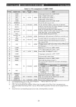
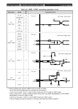
Table 5-1: Pin assignment of USER1 PORT
Pin No.
Signal name
Type
Voltage
level
Return
Detail
1
COMA
Analog signal common for USER1 PORT.
2
VOUT
AO
0-10V
COMA
Output voltage monitor signal
3
IOUT
Output current monitor signal *1
4
POUT
Output power monitor signal *1
5
COMA
Analog signal common for USER 1 PORT.
6
~
9
RESERVE
This is not used. Leave it open.
10
DC ON
DI
0-15V/24V
COMD The DC becomes unable to output only at LOW level.
11
READY
DO
0-15V/24V
COMD
Output at Low level when the output operation is possible.
(Low level even during the operation)
12
OUTPUT
Output at Low level during the output operation.
13
SETPOINT
Low-level output when the output values are within a certain
range with respect to the command values.
14
FAIL
Low-level output in the event of FAIL.
15
PARAMETER
SET
DI
0-15V/24V
COMD Switching the ARC parameter to HIGH is A, and LOW is B.
16
HARC
DO
0-15V/24V
COMD
Low-level output of 100us during hard-arc process.*3
17
MARC
Low-level output of 100us during micro-arc process.*3
18
AUX
15V
COMD
The output is +15V.
Although it can be used as the power-supply voltage for DO
of USER1 PORT of the power supply, do not use it for any
other purposes.
19
COMD
Digital signal common for USER 1 PORT.
20
COML
LEVEL signal common for USER 1 PORT.
21
LEVEL
AI
0-10V
COML Power output set voltage (0 to 10V)*1
22
COMA
Analog signal common for USER 1 PORT.
23
24
RESERVE
This is not used. Leave it open.
25
COMD
Digital signal common for USER 1 PORT.
26
RESET
DI
0-15V/24V
COMD
FAIL is reset at a low-level input.* 2
27
PSEL
The output control mode can be selected by the following
combinations:
Output control
mode
PSEL
(
27PIN
)
ISEL(28PIN)
Rated power control
Low
High
28
ISEL
Rated current control
High
Low
Rated voltage control
High
High
WARNING*4
Low
Low
29
~
33
RESERVE
This is not used. Leave it open.
34
COMD
Digital signal common for USER 1 PORT.
35
REMOTE
DO
0-15V/24V
COMD Output at Low level with the USER mode selected.
36
RESERVE
This is not used. Leave it open.
37
INTERLOCK
DI
0-15V/24V
COMD The interlock is released at Low level.
*1
It varies depending on the number of power supplies. *
(
Refer to Table 4-5 in item 4-6)
*2
Input Low level for 200msec or more.
*3
Even if the arc processing time setting is 100us or less, the output will be 100us. Even if arc processing is
performed multiple times during 100us, only one 100us output is generated. This time can be changed from the
menu.
*4
Since there is no corresponding output control mode, a warning will be processed.


