


DC Power Supply
【
DC-10-D/DC-20-D/DC-10-DH/DC-20-DH
】
4. Description of Functions
-19-
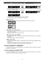
Table 4-3: Each operation mode and overview
Operation mode
Overview
LOCL
Operation on the front panel
USER
Operate with an external control device, such as a PLC, connected to USER1
PORT.
HOST
Operation through SERIAL communication (RS-232C, RS-485) PORT
HST+
Operate through the SERIAL communication PORT with USER1 PORT or USER2
PORT.
CSTM
The USER and HOST operation rights can be selected.
For the operation right in each operation mode, refer to Table 4-4.
Depending on the function, there are some processes that can accept multiple operations, such as the
reset signal (error clear signal).
Table 4-4: Operation rights in operation modes
Operation mode
LOCL
USER
HOST
HST+
CSTM
*1
Interlock
USER1 PORT
/USER2 PORT
USER1 PORT
/USER2 PORT
USER1 PORT
/USER2 PORT
USER1 PORT
/USER2 PORT
USER1 PORT
/USER2 PORT
Reset signal
Front panel
/USER1 PORT
/Communication
Front panel
/USER1 PORT
/Communication
Front panel
/USER1 PORT
/Communication
Front panel
/USER1 PORT
/Communication
Operation rights
selectable
Operation mode
change
Front panel
/Communication
Front panel
/Communication
Front panel
/Communication
Front panel
/Communication
Operation rights
selectable
Output control
mode change
Front panel
USER1 PORT
Communication
Communication
Operation rights
selectable
Command value
Front panel
USER1 PORT
Communication
Communication
Operation rights
selectable
Output ON/OFF
Front panel
USER1 PORT
/USER2 PORT
Communication
USER1 PORT
/USER2 PORT
Operation rights
selectable
Other parameter
settings
Front panel
/Communication
Front panel
/Communication
Front panel
/Communication
Front panel
/Communication
Operation rights
selectable
*1: CSTM allows you to set each operation right in the menu.
In all operation modes, it is necessary to release interlocks on pins between 37 and 34 of USER1
PORT or pins between 1 and 5 of USER2 PORT in order to output.
The interlock signal is included in the P/S cable in system operation (with multiple units connected),
and therefore it is not necessary to release the interlock at USER1 PORT or USER2 PORT for the
second and subsequent units (Unit2 and subsequent ones) that are connected in the system.
4-5 Output Control Mode Selection
You can select between constant voltage, constant current, and constant power control.
The setting method depends on the operation mode.
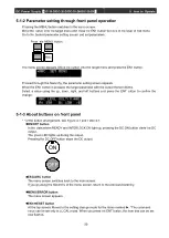
4-5-1 LOCAL mode setting
The settings can be made through operation on the front panel.
Make a selection in SET/SET/MODE in the parameter tree.
PSEL (Constant power control): Outputs can be produced by power control.
VSEL (Constant voltage control): Outputs can be produced by voltage control.
ISEL (Constant current control): Outputs can be produced by current control.


