background image

Chapter 7: Field Service Components

00.053.204, Revision A

SonixTouch Q+ Service Manual

7-22

35

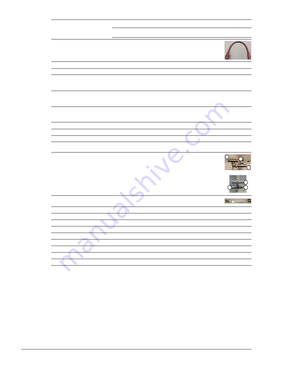
HDMI Connector 

Connects to the LCD display. 

Note:

 The LCD display must be connected to this specific HDMI connector or the

display will not work. 

36

HDMI Connector 

Connects to the DVI connector on the Back Connectivity Panel. 

37

HDMI Connector 

Not in use. 

38

USB Port 

Used by the optional SonixGPS (when applicable). (May or may not be present.) 

39

USB Port 

Not in use. (May or may not be present.) 

OR 

Used by the optional 

ECG

 module USB connection (when applicable). 

40

USB Port 

Not in use. (May or may not be present.) 

OR 

Used by the optional USB printer (when applicable). 

41

Display Port 

Not in use. (May or may not be present.) 

OR

Used by the optional 

ECG

 module (when applicable). 

42

RS232 Serial Port 

Not in use. (May or may not be present.) 

43

RS232 Serial Port 

Not in use. (May or may not be present.) 

44

RS232 Serial Port 

Not in use. (May or may not be present.) 

Power Hub 

A

Power Connector 
with 3-Way Adapter 

OR 

with 4-Way Adapter 

Used by the Speakers (1), ECG (2) and LED-lit Ultrasonix logo (3). 

B

Power Switch 
(with Splitter Bias Cable) 

Used by the system ON/OFF switch as well as for UPS power. 

C

Speaker Power Connector 

Used by the system speakers. 

D

5V Power Connector 

Not in use. 

E

5V Power Connector 

Not in use. 

F

5V Power Connector 

Used by the LED-lit Ultrasonix logo. 

G

5V Power Connector 

Used by the optional 

ECG

 module (when applicable). 

H

5V Power Connector 

Used by the optional SonixGPS (when applicable). 

I

12V Power Connector 

Used by the optional SonixGPS (when applicable). 

J

12V Power Connector 

Not in use. 

K

System Power Switch 

Used as the ON/OFF switch by the operator console. 

2

1

3

2

1

3

Содержание SonixTouch Q+

Страница 1: ...Analogic Ultrasound Service Manual SonixTouch Q Ultrasound System...

Страница 2: ......

Страница 3: ...hmond BC V6V 2K9 Canada www analogicultrasound com support ultrasonix com 1 866 437 9508 1 604 279 8550 1 778 296 3860 Support 2014 Analogic Corporation 00 053 204 Revision A June 27 2014 All Rights R...

Страница 4: ......

Страница 5: ...Wired Network Connection 3 4 3 1 5 3 Image Management Network 3 4 3 2 PRE INSTALLATION 3 5 3 2 1 Preliminary Inspection 3 5 3 2 2 Unpacking Instructions 3 5 3 2 2 1 Unpacking a System 3 6 3 3 INSTALL...

Страница 6: ...e Service Mode Option 7 7 7 1 6 Restoring Importing Patient Data via the Service Mode Option 7 9 7 2 TURNING THE UPS BREAKERS ON AND OFF 7 11 7 2 1 Determining Whether the UPS Breakers are ON or OFF 7...

Страница 7: ...twork 8 15 8 2 3 Configuring DICOM 8 15 8 2 3 1 Local Host 8 15 8 2 3 2 DICOM Storage Settings 8 16 8 2 3 3 Custom Keys and DICOM Store 8 19 8 2 3 4 DICOM Print Settings 8 20 8 2 3 5 DICOM Worklist Se...

Страница 8: ...3 3 2 Storing and Packaging 11 9 11 3 4 General Transducer Cleaning Disinfecting Recommendations and Warnings 11 10 11 3 5 Cleaning Disinfecting Non Invasive Transducers 11 11 11 3 5 1 Cleaning Non In...

Страница 9: ...lable on all platforms Therefore some service instructions will apply only to specific models configurations Caution United States law restricts this device to sale or use by or on the order of a Phys...

Страница 10: ...ll terminate Further because unauthorized use of such computer programs will leave Ultrasonix without an adequate remedy at law Buyer agrees that injunctive or other equitable relief will be appropria...

Страница 11: ...ulti position articulated lift system operator console modulo transducers and UPS Figure 1 1 System Components Table 1 1 System Components 1 LCD display 2 Power button 3 Operator console with touch sc...

Страница 12: ...e modulo helps to ensure that no data is lost when the system is temporarily unplugged and moved around Upon delivery the UPS will be turned off and the battery may be completely drained of power Duri...

Страница 13: ...10 and 200 240V 10 Measurement Metric Value US Value Width 53 5 cm 21 in Depth 91 5 cm 36 in Height highest position measured from top of LCD display to floor 155 cm 61 in Height lowest position meas...

Страница 14: ...Chapter 2 System Specifications 00 053 204 Revision A SonixTouch Q Service Manual 2 2...

Страница 15: ...ing Shipping Storage Pressure 50 kPa to 106 kPa Warning Operate in an indoor environment only free from moisture flammable liquids gases corrosive substances strong electrical or magnetic fields and e...

Страница 16: ...ospital grade power cord as follows Table 3 7 Hospital Grade Power Cord Specifications Electrical Rating Value Measurement System Only 100V 120V 50 60 Hz 200V 240V 50 60 Hz Current Draw System Only 12...

Страница 17: ...uch as an ESD strap 3 1 4 Electromagnetic and Radio Frequency Interference This equipment has been tested and found to comply with the EMC limits for EN 55011 Group 1 Class A and EN 60601 1 2 These li...

Страница 18: ...e is CAT5 Category 5 10 Base T unshielded twisted pair 3 1 5 3 Image Management Network Obtain the following information from the system administrator list of all equipment that is part of the Image M...

Страница 19: ...urred during transport 2 Look for evidence to ensure that the crate has not been opened 3 Examine the Tip n Tell attachment on the outside of the package to ensure the crate has not been tipped too fa...

Страница 20: ...ve the cardboard cover 3 Lift off the plastic bag covering the system 4 Remove the following items from the system front license setup card and USB key rear document envelope Caution Stand out of the...

Страница 21: ...f the padding protecting the neck of the LCD display stand 7 At the rear of the system slice the tape holding the foam together and remove the foam loops from the rear handles 8 Remove the foam bendin...

Страница 22: ...Manual 3 8 9 Remove the foam packing from the sides of the system 10 Remove any transducers and biopsy kits packed around the system 11 Remove the foam packing from around the front wheelbase 12 Undo...

Страница 23: ...the system back lifting the front wheels clear the foam depressions 16 Using the pre cut slit in the white foam ramps insert them onto the unfolded cardboard and align them with the wheels Note The sy...

Страница 24: ...ely unlocked 18 Depending on whether the system is being unloaded from the front or back of the packing crate use the rear handles to push or pull the system down the ramps and off the palette Caution...

Страница 25: ...m moves freely in any direction 3 3 1 2 LCD Display Tip rotate the LCD display to ensure that it tips forward and back as required rotates from side to side stays firmly in position once the required...

Страница 26: ...dles to gently rock the console forward or backward until the desired tilt is achieved 3 Pull backward on the lever under the right side of the console to lock the console in place To Swivel the Conso...

Страница 27: ...trols the system voltage setting When changing the voltage settings the EMI filter must be adjusted to the relevant setting and the fuses must be flipped to match the selected voltage Refer to 3 3 3 2...

Страница 28: ...ge Settings 1 Power off and unplug the power cord from both the wall outlet and the system 2 Use the screwdriver to open the fuse box lid 3 Position the screwdriver at the top as in step 2 using it to...

Страница 29: ...d to the AC power cord receptacle Figure 3 5 3 Plug the power cord into a wall outlet hospital grade electrical outlet recommended 3 3 3 1 Turning on Main Power Switch To Turn on Main Power Switch 1 P...

Страница 30: ...lug the power cord from both the wall outlet and the system 2 Use the screwdriver to open the fuse box lid 3 Position the screwdriver at the top as in step 2 using it to remove the fuse box 4 Replace...

Страница 31: ...2 Press the top of the breaker to turn it on 1 Battery Breaker 2 AC Input Breaker 3 System front Warnings NEVER let liquid from any source enter the UPS Failure to do this may result in accidental sh...

Страница 32: ...wer cord to a wall outlet 6 Press and hold the console POWER button for one second to turn on the system 7 Power off and unplug the system Caution It is important to turn on the breakers in the order...

Страница 33: ...e power cord 4 Press and hold the console POWER button for one second 5 Inform the facility s representative that the system is installed and ready for any safety testing they would normally conduct 6...

Страница 34: ...own and place it on a secure surface 2 Orient the printer so the front 1 faces forward 3 Using the two supplied screws 2 attach the mounting plate to the printer 4 Continue to the next set of instruct...

Страница 35: ...1 Using the two supplied thumbscrews 1 attach the printer mounting plate to the system 2 Plug the USB cable extending from the system s cable chase 1 into the USB connector on the printer 2 3 To mini...

Страница 36: ...ch the peripheral tray basket to the peripheral tray while the tray is attached to the system 3 3 7 4 USB Printer Mounted on the Peripheral Tray If Applicable If the system order included the peripher...

Страница 37: ...y need to be connected 3 To help prevent cable clutter the power cable is held in place with self adhesive cable clips with enough slack to connect it to the system If desired during use excess slack...

Страница 38: ...ual 3 24 3 4 SET SYSTEM DATE AND INSTALL LICENSES Follow the instructions on the Setup License card included with the system Note The instructions on the Setup License card must be completed in the pr...

Страница 39: ...the system to B Mode tap the touch screen the B button ensuring that it changes to a solid green color 1 QSONIX button 4 FREEZE button 2 SELECT button 5 Touch screen 3 UPDATE button 6 Touch screen di...

Страница 40: ...USB media memory stick external hard drive etc extra HDMI compatible LCD display 6 6 4 4 UPS TEST IF APPLICABLE To Test the UPS 1 Ensure that the UPS has been configured 3 3 4 2 Ensure the system is p...

Страница 41: ...6 LICENSES Check system licenses to ensure at least some licenses are Enabled If no licenses are Enabled repeat section 3 4 Set System Date and Install Licenses To Check System Licensing 1 Tap the tou...

Страница 42: ...Chapter 4 Performance Testing 00 053 204 Revision A SonixTouch Q Service Manual 4 4...

Страница 43: ...he Internet 1 Ensure the system has a live Internet connection 2 Tap the touch screen Menu button 3 Select Administrator Software Updates 4 The system will default to the Update Location Internet Upda...

Страница 44: ...2 Connect the USB device to one of the system s external USB ports 3 Tap the touch screen Menu button 4 Select Administrator Software Updates 5 From the Update Location drop down menu select the relev...

Страница 45: ...e 3 Enter the Service Password and select OK 4 From the Advanced Tools and Options drop down menu select Show Hide Protocols 5 Select Go to access the Protocols Settings dialog 6 Select deselect the r...

Страница 46: ...dministrator Patient Repair Database 3 Select OK to exit 5 4 SYSTEM RECOVERY Before performing a system recovery consult Ultrasonix Technical Support as this should only be done as a last resort Techn...

Страница 47: ...determine the exact make s model s of Ultrasonix approved devices Warning It is the Operator s responsibility to ensure that any peripheral device placed within the patient environment including prin...

Страница 48: ...reference for installing other system network printers To Connect the Network Printer to the System 1 Tap the touch screen Menu button 2 Select Administrator Peripherals 3 In the Paper Printer dialog...

Страница 49: ...ng 1 Tap the touch screen Menu button 2 Select Administrator Custom Keys 3 Select the desired Custom Key tab 4 Select the Printer checkbox 5 Select OK 6 3 3 2 Trigger Configuration To Configure the Cu...

Страница 50: ...pply special commands as required enter the desired text in the space provided 7 Select OK Note The default is set to print as two columns by three rows for a total of six images per sheet Before the...

Страница 51: ...ls Footswitch Table 6 3 Footswitch Options Warning Footswitch is rated IPX1 only Do not expose to liquids Enable BNC Footswitches Ensure an Ultrasonix approved Footswitch has been connected then selec...

Страница 52: ...or HDMI Warnings USE OF CONTROLS or adjustments or performance of procedures other than those specified in the manufacturer s User s Guide delivered with system may result in hazardous laser light exp...

Страница 53: ...e end of the DVI cable to DVI on the system s Back Connectivity Panel 2 Connect the other end of the DVI cable to DVI Input on the TV 3 Ensure the TV is plugged in 4 Power on the TV 5 Power on the sys...

Страница 54: ...nect one end of the DVI cable to DVI on the system s Back Connectivity Panel 2 Connect the other end of the DVI cable to PC In on the TV 3 Ensure the TV is plugged in 4 Power on the TV 5 Power on the...

Страница 55: ...clude models that are no longer offered for sale Ultrasonix reserves the right to update edit this list at any time Table 6 6 Transducers not to scale SA4 2 24 Phased Array PA7 4 12 Phased Array HST15...

Страница 56: ...and Accessories 00 053 204 Revision A SonixTouch Q Service Manual 6 10 m4DC7 3 40 Mini Motor driven Curved Array 4DEC9 5 10 Motor driven Endocavity Microconvex Array EC9 5 10 and EC9 5 10 GPS Endocav...

Страница 57: ...ensure access to this data if either the modulo or hard drive needs replaced during servicing The following options are available for export Imaging Presets 3D 4D Presets DICOM Server Configuration Se...

Страница 58: ...n step 6 a completion dialog will be presented when the export process has finished this will take approximately 15 45 seconds Note When creating a backup prior to servicing or replacing the modulo Ul...

Страница 59: ...guration Settings Measurement Order Obstetrical Tables Protocols General Preset Assignments Measurement Customization Worksheets Banners SonixHub Worksheets General Protocol Equipment Tools Required U...

Страница 60: ...Import 5 Check the items to be imported 6 Select OK to begin the import process or Cancel to exit without importing Caution Ultrasonix does not recommend importing user defined Presets created with a...

Страница 61: ...ort Destination 6 Select the Export button to begin the backup 7 When the Export is complete the following message will be presented Note When creating a backup prior to servicing the modulo be sure t...

Страница 62: ...d on the left hand side of the Exam Import Export page select all data for import 5 Select the Import button to begin the procedure 6 When the Import is complete the following message will be presente...

Страница 63: ...at least 5 Gb of available space To Backup Export Patient Data via the Service Mode Option 1 Connect the USB keyboard to the one of the four USB ports 2 Connect the USB storage device to the one of th...

Страница 64: ...kup 10 If the USB device already contains patient data the following message will be displayed Select OK to continue or Cancel to exit without creating a backup 11 Once the procedure is complete the f...

Страница 65: ...de Option 1 Connect the USB keyboard to the one of the four USB ports 2 Connect the USB storage device to the one of the three remaining USB ports 3 Tap the touch screen Menu button 4 Select Administr...

Страница 66: ...entInfo folder already exists on the system the following warning will be presented Select Yes to continue or No to exit without restoring Patient Exam data 11 When Patient Exam data already exists on...

Страница 67: ...the power cord is disconnected from any power source 2 Turn 2 AC Input Breaker to the OFF position 3 Turn 1 Battery Breaker to the OFF position Note Breaker access is at the bottom of side shroud B F...

Страница 68: ...Battery Breaker to the ON position 3 Turn 2 AC Input Breaker to the ON position Warning Do not perform any internal system maintenance if the UPS breakers are turned on Note Breaker access is at the b...

Страница 69: ...de Shrouds Figure 7 3 Right and Left Side Shrouds Note Because the modulo is accessible from the side of the system not all service tasks necessitate its removal Warning Do not perform any internal sy...

Страница 70: ...Using a 4mm Allen key give each of the two shroud fasteners a quarter turn to the left 4 Grasp the shroud by the sides and tip the top outwards 5 Ensure the bottom sides of the shroud are clear of th...

Страница 71: ...ing a 4mm Allen key give each of the two shroud fasteners a quarter turn to the left 4 Grasp the shroud by the sides and tip the top outwards 5 Ensure the bottom sides of the shroud are clear of all c...

Страница 72: ...the shroud into place 4 Using a 4mm Allen key position the two fasteners and give each a quarter turn to the right To Reinstall the Left Side Shroud 1 Insert the tabs on the bottom of the shroud into...

Страница 73: ...ables connections on the System Case Connectivity Panel cutting cable ties only as needed 4 Using the 10mm socket wrench undo the nut and washer securing the grounding mesh from the modulo to the cons...

Страница 74: ...d UPS output power cable 3 7 Using the 4mm Allen key undo the two screws and washers securing the modulo to the front of the system frame 8 Using the 2 Phillips screwdriver undo the four screws securi...

Страница 75: ...lo to the side system frame 3 Using the 4mm Allen key fasten the two screws and washers securing the modulo to the front of the system frame 4 Connect the three bottom left rear power cables connected...

Страница 76: ...eatly fasten all cables keeping them tucked out of the way 10 Reinstall both side shrouds 7 2 6 7 3 3 Connectivity Once the modulo has been replaced all cables and wiring must be properly reconnected...

Страница 77: ...Connectivity Panel This port supports 10 100Mb 18 XTA Vdriver Serial Connector Used by the serial ECG OR Not in use May or may not be present 19 Console Power Connector Used by the operator console 20...

Страница 78: ...CG module when applicable 42 RS232 Serial Port Not in use May or may not be present 43 RS232 Serial Port Not in use May or may not be present 44 RS232 Serial Port Not in use May or may not be present...

Страница 79: ...ader memory stick etc LAN Use to connect the system to a network This port supports 10 MB 100 MB 1 BNC Input Connector Connected to the console 1 button use to connect an Ultrasonix approved periphera...

Страница 80: ...Presets button and select the relevant transducer 8 Ensure that the system is imaging properly i e there are no oddities such as black lines excessive noise etc 9 Once the system is working power it o...

Страница 81: ...the power cord 2 Press the console POWER button to turn on the system 3 After initialization plug in a transducer 4 Press the console button and select the relevant transducer 5 Tap the touch screen...

Страница 82: ...ered down unplugged and all transducers have been disconnected 2 Remove the side shrouds 7 2 5 7 4 2 Opening the Front Block Ultrasound Module To open the front block ultrasound module without removin...

Страница 83: ...e sure the cables are moved out of the way 4 Gently pull the modulo forward about an inch until the Service Access screws are accessible Note In order to access the screws holding the Front Block Ultr...

Страница 84: ...nfasten the two screws securing the Front Block 7 Swing open the Front Block Ultrasound Module to expose the interior Caution When pushing the modulo forward take care to ensure that the cabling is pr...

Страница 85: ...2 Phillips screwdriver To Remove the Front Block Ultrasound Module 1 With the Front Block Ultrasound Module partially open locate the cable tie securing the PCI cables to the inside of the door Reach...

Страница 86: ...rior of the modulo remove the two screws fastening the Side EMI Strip over the door hinges 4 Remove the modulo door hinge cover from inside the modulo and expose the two hinges 5 To remove the door us...

Страница 87: ...le 1 Attach the new front block ultrasound module using the 2 Phillips screwdriver to fasten the two hinges two screws per hinge 2 From the exterior of the modulo using the 2 Phillips screwdriver fast...

Страница 88: ...top right hand side of the front block ultrasound module Note The ribbon cables coming from the PCI card are connected in reverse The top cable from the PCI card 1 is connected to the bottom PCI conn...

Страница 89: ...SonixTouch Q Service Manual 00 053 204 Revision A Chapter 7 Field Service Components 7 33 6 Thread a cable tie through the cable tie anchor on the inside of the modulo door...

Страница 90: ...y tucking in all cables so they cannot interfere with any internal fans This will also ensure that no undue stress is placed upon the cables the next time the front block is opened 3 Using the 2 Phill...

Страница 91: ...tal shorts shocks or electrocutions DO NOT attempt to service this product yourself Attempting to open the UPS may cause exposure to lethal voltages within the unit even when it is apparently not oper...

Страница 92: ...er to the system 2 Tap the touch screen Presets button and select the relevant transducer 3 Gently slide the edge of any coin along the transducer face to test for a line s or shadow s in the image on...

Страница 93: ...relevant transducer 4 Test the transducer by taking a fresh image If the line shadow s in the image disappears then the transducer board is the problem and the front block ultrasound module rather tha...

Страница 94: ...Figure 7 8 Transducer Holders and Cable Hooks Table 7 3 Transducer Holders and Cable Hooks Note For best results Ultrasonix recommends removing the transducer holders before cleaning 11 2 8 This will...

Страница 95: ...ed with the exception of the peripheral tray basket The basket will have to be installed after delivery 7 8 2 1 Attaching Detaching the Peripheral Tray Basket To Attach Detach the Peripheral Tray Bask...

Страница 96: ...ctions 7 9 1 and 7 9 2 Note The RMA number must always be clearly written on the outside of the packaging Warnings The UPS breakers MUST be turned OFF 7 2 2 when shipping by air or ground This applies...

Страница 97: ...work Configuration system network connectivity 8 2 DICOM Configuration Figure 8 1 DICOM Configuration Notes When using a hard wired network connection ensure the network is connected via a CAT5 cable...

Страница 98: ...ngs dialog offers basic and advanced settings for configuring the system for DICOM image storage To Access DICOM Storage Settings 1 Tap the touch screen Menu button 2 Select Administrator DICOM Storag...

Страница 99: ...ication request to DICOM Storage Device ping to verify connection Settings Select to access Storage Settings Figure 8 4 and Table 8 3 Application Entity AE Note The data entered edited in the followin...

Страница 100: ...s Compression Preferences Single Frame JPEG Lossless JPEG Lossless SV1 RLE Lossless JPEG Lossy No Compression Set DICOM image format storage order for single frame images Note Refer to the DICOM Stand...

Страница 101: ...failed storage attempt 1 1000 The default is 50 Note Failure may occur during DICOM file creation or DICOM file transfer The retry setting applies to both failure types Create New Error File Days Sel...

Страница 102: ...in the Before and After images Figure 8 6 DICOM Storage Settings Brightness Contrast Table 8 5 DICOM Storage Settings Brightness Contrast Contrast Adjusts the level of Contrast applied to the images B...

Страница 103: ...Figure 8 7 DICOM Storage Settings SonixHub Settings Table 8 6 DICOM Storage Settings SonixHub Settings Note These settings are only available if SonixHub is licensed Embed Cine As Is Select to send Ci...

Страница 104: ...configured during data transfer the Operator has the option of selecting which Print Server s will receive the data These options are only available when a Device is or has been added Name Enter sele...

Страница 105: ...iguration Print Settings Table 8 8 DICOM Print Settings AE Configuration Print Settings Image Density Format Print in Color Select to print images in color Deselect to print grayscale default Columns...

Страница 106: ...e Orientation of the print page Portrait or Landscape Size Select the Size of the print page Magnification Select the method of Magnification Replicate Bilinear Cubic or None Smoothing Select the Smoo...

Страница 107: ...n in the Before and After images Figure 8 11 DICOM Print Settings Brightness Contrast Table 8 10 DICOM Print Settings Brightness Contrast Contrast Adjusts the level of Contrast applied to the images B...

Страница 108: ...t Service Class User SCU Figure 8 12 DICOM Worklist Device Test Results To Access DICOM Worklist Settings 1 Tap the touch screen Menu button 2 Select Administrator DICOM Worklist Note All Modality Per...

Страница 109: ...three AE fields AE Title IP Address and Port Add Select to Add the new AE Worklist Device Delete Select to Delete the selected AE Worklist Device Test Select to send verification request to DICOM Work...

Страница 110: ...ver Address es 8 2 1 2 DICOM SCU The following details are required for the local Application Entity i e DICOM client side Station Name AE Title 8 2 1 3 DICOM SCP Obtain the DICOM SCP details listed b...

Страница 111: ...2 Select Administrator DICOM 3 If required update Station Name and AE Title to match the data collected in 8 2 1 2 4 The Storage Commitment AE data should be edited only by a highly competent IT Admin...

Страница 112: ...he SonixHub checkbox 1b SonixHub Settings tab 2 and configure the fields as required 2a Embed Cine As Is and Send SonixDVR Videos Note As far as DICOM is concerned the device Name is meaningless Becau...

Страница 113: ...Tap the touch screen Menu button 2 Select Administrator DICOM Storage 3 Under Devices highlight the relevant Name 4 Select Test to activate the C Echo command for the highlighted SCP 5 If successful t...

Страница 114: ...Images 6 Select OK to accept the changes or Cancel to exit without saving To Configure Global Storage Settings 1 Tap the touch screen Menu button 2 Select Administrator DICOM Storage Global Storage Se...

Страница 115: ...the touch screen Menu button 2 Select Administrator DICOM Storage 3 Under Devices highlight the relevant Name 4 Select Delete to remove the device from the list 5 Repeat step 3 and step 4 as many time...

Страница 116: ...pt the changes or Cancel to exit without saving To Test DICOM Print Devices 1 Tap the touch screen Menu button 2 Select Administrator DICOM Print 3 Under Devices highlight the relevant Name 4 Select T...

Страница 117: ...appropriate Brightness and Contrast levels 4 Select OK to accept the changes or Cancel to exit without saving To Configure AE Configuration Specific Print Settings 1 Tap the touch screen Menu button 2...

Страница 118: ...anced Print Settings as required 4 Select OK to accept the changes or Cancel to exit without saving To Delete DICOM Print Devices 1 Tap the touch screen Menu button 2 Select Administrator DICOM Storag...

Страница 119: ...r Devices highlight the relevant Name 4 Select Test to activate the C Echo command for the highlighted SCP 5 If successful the Test result will produce a message similar to this example 6 Select OK to...

Страница 120: ...Chapter 8 DICOM 00 053 204 Revision A SonixTouch Q Service Manual 8 24...

Страница 121: ...ion requires a third party USB modem Contact your dealer or Ultrasonix Technical Support to learn more about this option Caution System networking options are intended for use inside your organization...

Страница 122: ...is an Internet connection available Remote Support After receiving a PIN Personal Identification Number from Ultrasonix use this option to connect to the Internet This will allow an Ultrasonix Support...

Страница 123: ...located on the Back Connectivity Panel 2 Tap the touch screen Menu button 3 Select Administrator Network Internet Connection using LAN 4 Select TCP IP Settings 5 Under General select Obtain an IP addr...

Страница 124: ...other end of the modem to a telephone jack in the wall 3 Tap the touch screen Menu button 4 Select Administrator Network Dialup Internet Connection 5 Complete the Account Information and Options sect...

Страница 125: ...Figure 9 4 Network Configuration Page Wireless Figure 9 5 Wireless Network Connection Setup Table 9 2 Wireless Network Connection Setup 1 Security Indicator 2 Wireless Signal Strength Indicator Notes...

Страница 126: ...on 2 Select Administrator Network Wireless Settings 3 Complete the wireless connection following the onscreen directions in the Wireless Network Connection dialog 4 Select OK and press the console but...

Страница 127: ...button 2 Select Chat Support 3 If an Agent is logged on refer to the message at the bottom of the Chat Request Form use the keyboard to complete the Chat Request Form 4 Select Request Chat 5 When the...

Страница 128: ...PIN Personal Identification Number provided by Ultrasonix Technical Support 4 When prompted select Download Run Run in order to install the required programs 5 The system can now be remotely controll...

Страница 129: ...ive etc To Obtain and Copy License key onto the System 1 Tap the touch screen Menu button 2 Insert the USB media into one of the available USB ports 3 Select Administrator Licensing 4 Make note of the...

Страница 130: ...utton 2 Insert the USB media into one of the available USB ports 3 Select Administrator Licensing 4 Select Local Drive 5 Select the drive containing the license key file for example USB Data AC F 6 Se...

Страница 131: ...Procedure Frequency 11 2 CLEANING SYSTEM COMPONENTS Ultrasonix recommends the following cleaning instructions for all external surfaces including the cart cables and connectors Test Clean Frequency In...

Страница 132: ...l Alcohol Cautions Power off and unplug the system prior to cleaning the LCD display DO NOT apply cleaning solutions directly to any surface of the LCD display or cabinet Caution Computer wipes may be...

Страница 133: ...l amount of one of the following recommended cleaning solutions to a soft non abrasive cloth and wipe the wireless adapter water mild detergent PH level at or near 7 and water solution 11 2 7 SonixGPS...

Страница 134: ...t PH level at or near 7 and water solution Cautions Power off and unplug the system prior to cleaning For best results Ultrasonix recommends removing the transducer holders and cable hooks before clea...

Страница 135: ...stem fan filter is cleaned early ie before the system fan filter cleaning reminder is displayed the cleaning reminder clock should be reset To Reset the System Filter Cleaning Reminder 1 Tap the touch...

Страница 136: ...system 11 2 11 2Cleaning the Modulo Fan and Exhaust Filters Equipment Tools Required 2 Phillips screwdriver To Clean the Modulo Fan and Exhaust Filters 1 Power off and unplug the system 2 Remove the s...

Страница 137: ...system has many fans located in different areas Fans tend to accumulate the largest amount of dust within the modulo The places to check are listed below Use the procedures in section 7 3 Replacing th...

Страница 138: ...transvaginal transesophageal etc ensure the transducer is covered with the appropriate STERILE transducer cover sheath which has received regulatory clearance for use Refer to Third Party Accessories...

Страница 139: ...autions DO NOT drop the transducers DO NOT hit the transducers against any surface that can dislodge or damage any of the transducer components DO NOT pinch or kink the transducer cable DO NOT use a b...

Страница 140: ...g safety procedures involving personal protective equipment such as gloves protective eyewear and protective clothing DO NOT use sterilization or disinfection methods that have not been recommended by...

Страница 141: ...ivated Dialdehyde Solution 14 day Cidex Plus 28 day Cidex OPA Cidezyme Klenzyme McKesson Brand Metrizyme Milton Disinfecting Liquid Nuclean Omnicide FG2 Steranios 2 T spray M ISCELLANEOUS SA4 2 24 PA7...

Страница 142: ...cleaning always remove covers accessories and attachments To Clean a Transducer 1 After every patient exam wipe the ultrasound transmission gel off the transducer 2 Wipe the transducer and cable with...

Страница 143: ...NFECTING AGENTS Cidex Activated Dialdehyde Solution 14 day Cidex Plus 28 day Cidex OPA Cidezyme EC9 5 10 EC9 5 10 GPS 4DEC9 5 10 BPC8 4 10 BPL9 5 55 Caution Use only Ultrasonix recommended cleaners di...

Страница 144: ...nsibility to ensure each transducer is disinfected prior to shipping 11 3 5 and 11 3 6 the transducer is properly packaged for shipment 11 3 3 2 all shipping waybills paperwork is completed as per the...

Страница 145: ...environment Immunity Test IEC 60601 Test Level Compliance Level Electromagnetic Environment Guidance Electrostatic discharge ESD IEC 601000 4 2 6 kV contact 8 kV air 6 kV contact 8 kV air Floors shou...

Страница 146: ...t be predicted theoretically with accuracy To assess the electromagnetic environment due to fixed RF transmitters an electromagnetic site survey should be considered If the measured field strength in...

Страница 147: ......

Страница 148: ...MA 01960 USA Tel 1 978 326 1300 Fax 1 978 326 1399 info analogicultrasound com analogicultraound com Analogic Ultrasound Headquarters Canada Ultrasonix 130 4311 Viking Way Richmond BC Canada V6V 2K9 C...

Отзывы: