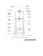
B. LIFT FRAME ASSEMBLY
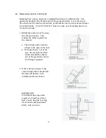
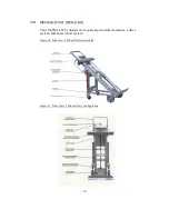
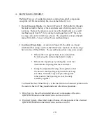
The Lift Frame is of welded aluminum construction and the sides of the frame fit inside
the Main Frame. The Drive Screw, which is fixed at top and bottom to the Main
Frame, passes through a device called a ball nut which is bolted o the top cross brace of
the Lift Frame. Rotation of the Drive Screw moves the Lift Frame relative to the Main
Frame via the bearings in the ball nut.
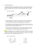
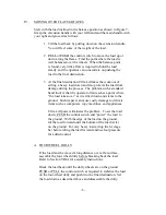
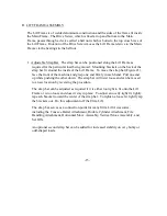
1. Adjustable Strap Bar. The strap bar can be positioned along the Lift Frame as
required for the particular load being moved. Mounting brackets on the back of the
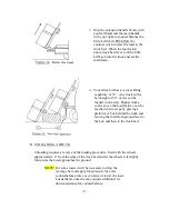
strap bar fit around the inside of the Lift Frame. To move the strap bar (Figure 21),
face the front of the machine and grasp one end firmly in each hand. Pull one end
up while pushing the other down. The strap bar will twist loose and can be moved
to a new location by reversing the procedure.
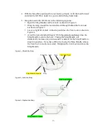
The strap bar can be adjusted as required if it is either too tight to fit onto the Lift
Frame or is too loose and doesn’t stay in place. To adjust an overly tight fit, lightly
tap each bracket toward the center of the strap bar. To tighten a loose fit, lightly tap
the brackets out. Do this adjustment off the Ultra Lift.
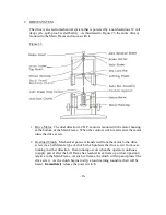
The strap bar serves as a connection point for many Ultra Lift Accessories,
including the Concave Barrel Attachment, Double Cylinder Attachment, File
Handling Attachment, Horizontal Move Assembly, Vertical Move Assembly, and
Set Offs.
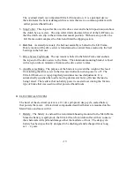
An optional second strap bar can be added for increased stability on very bulky or
odd-shaped loads.
-15-
Содержание 1500
Страница 28: ... ii ...

