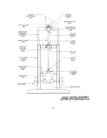
A. MAIN FRAME ASSEMBLY
The Main Frame is of welded aluminum construction and all components,
except the Lift Frame and strap bar, are attached directly to it.
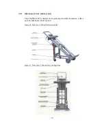
1. Frame Extension Handle. As shown in Figure 21, the handle fits through
brackets welded to the top of the main frame and is held in place by two
lock pins. Remove the pins to raise or lower the handle and vary overall
machine height from 62” (for working in tight quarters) to 72” for extra
leverage and control of tall, heavy loads. The adjustable extension handle
makes Ultra Lift a “one size fits all” powered hand truck.
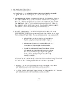
2. Fold Out 4 Wheel Dolly. As shown in Figure 20, the dolly is a tripod
attachment that swings out from the Main Frame and locks to the leverage
bar to form a 4 Wheel Dolly. The assembly procedure takes just seconds:
•
Release the leverage bar from its stored position
by removing the lock pin that holds it in place.
•
Release the tripod legs by turning the swivel lock
that holds the tripod against the main frame.
•
Swing the tripod and leverage bar together so that
the holes in the tripod legs align with the leverage
bar tubes. Slide the large lock pins through the
tubes and into the tripod legs to lock the dolly
assembly together.
To dissemble the 4 Wheel Dolly, set the load down in a balanced position with
the caster wheels off the ground and reverse the above procedure.
3. Drive System. Described in detail below, all components of the drive
system are mounted on the Main Frame and move with it.
4. Electrical System. Described in detail below, all components of the electrical
system are mounted on the Main Frame and move with it.
-14-
Содержание 1500
Страница 28: ... ii ...

