


VersaMux-4000
DNE Technologies
DNE Technologies
DNE Technologies
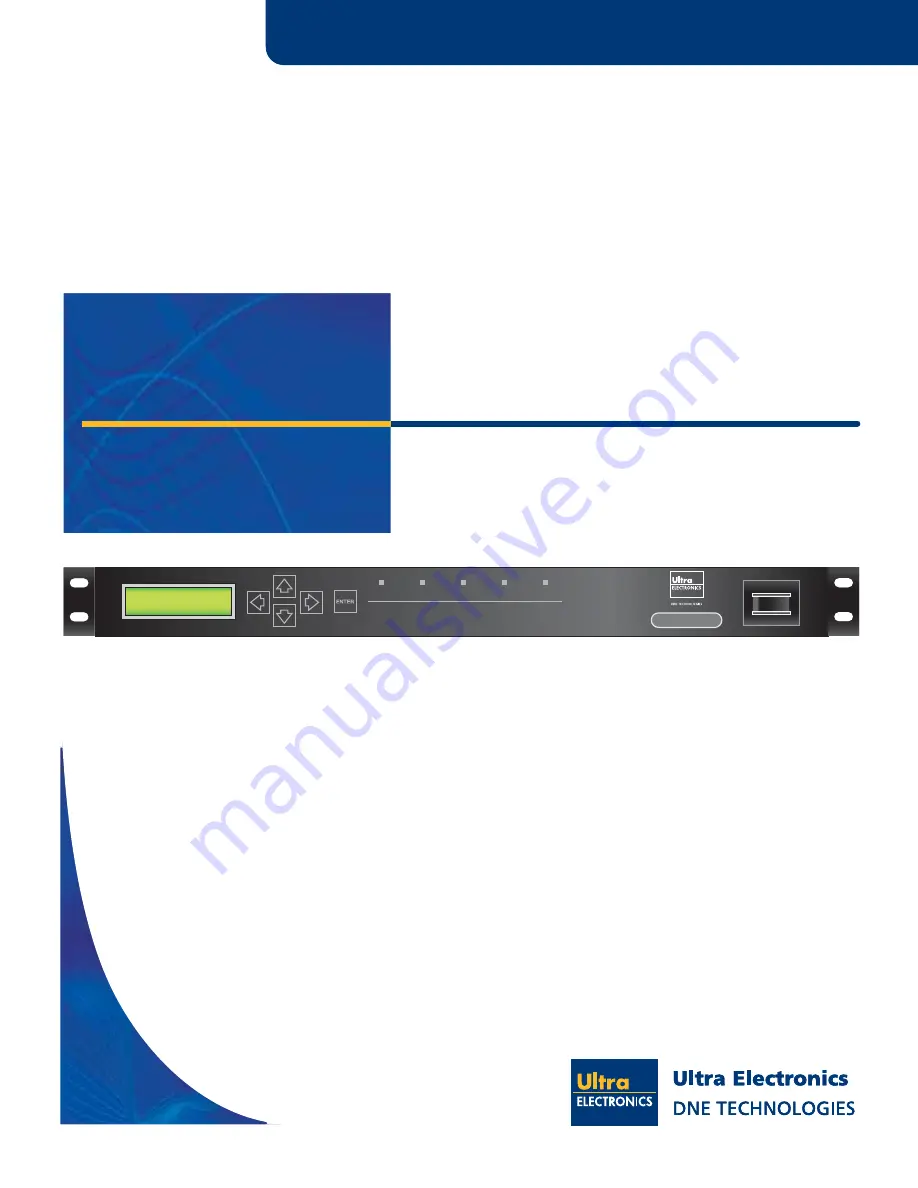
Trunk Group Multiplexer
System
POWER
AGGR
CLK REF
PORTS
FAULT
VersaMux-4000
0
I
This document, and the technical data within, is controlled for export
by the United States Department of State. It, or any part thereof, may
not be exported or transferred to any foreign person either in the
United States or abroad, or disclosed to a national of another country
without the prior written approval of the United States Department of
State.
VersaMux-4000
Trunk Group Multiplexer
Operation & Installation Guide
Part No. 24001157
Revision C


