IM_ONE_Safety-07
www.ueonline.com
6
The One Series
Field Safety System™
enclosure includes two conduit openings,
one intended for the high-power SAFETY RELAY OUTPUT (SRO) wiring and the
other intended for low-level signal and analog 4-20 mA wiring. 4-20 mA signals
shall be wired using a shielded/twisted pair to minimize the effects of electrical
interference. Please follow local electrical code requirements for explosion/flame
proof instrumentation.
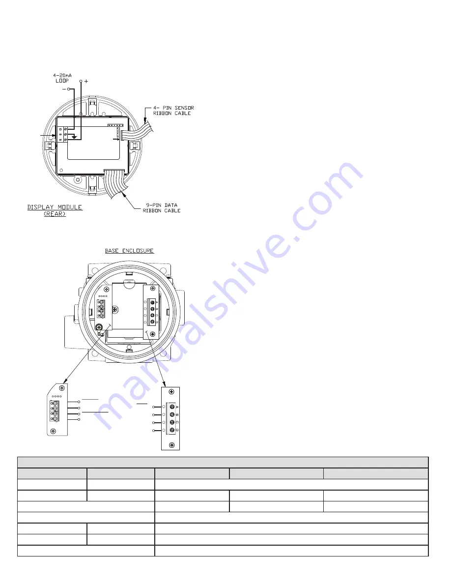
The diagrams in Figures 5 and 6 provide a rear view of the display module after
it has been removed from the base enclosure and an inside view of the base
enclosure circuit boards. Terminal Block 1 (TB1) is located on the display module.
All other terminal blocks (TB2 - TB4) are located inside the base enclosure.
Model 2SLP is loop-powered and is connected directly to an analog input of a PLC
or DCS via TB1 providing a 4-20 mA analog signal (see Table 3). (Polarity must
be observed). The loop connection powers the entire One Series
Field Safety
System™
, including the Safety Relay Output switch actuation. The auxiliary SAFETY
RELAY OUTPUT is connected via TB2 and is intended to switch an external load.
Refer to Table 3 for the SAFETY RELAY OUTPUT switch ratings.
Figure 6 shows the switch wiring connections located at TB2, TB3 and TB4 inside
the base enclosure. TB2 A and B terminals are provided for the external power
supply inputs to be switched by the Safety Relay Output. The SRO at TB2 C and D
terminals provide connections to the Safety Relay Output switch. Polarity must be
observed on all VDC switches. Please refer to the wiring diagrams shown on page
7.
The SRO Monitor function, if used, requires a connection to VDC (+) or VDC (-)
depending on whether the SRO circuit arrangement is sinking or sourcing (either
Neutral1 or Neutral2 for model 2SLP47). This connection allows the SRO current
to be measured that is sent out to an external load (final element), allowing the
IAW
TM
diagnostics to determine the integrity of the SRO wiring and if the SRO is
functioning properly.
NOTE:
As an alternative to loop power, model 2SLP may be wired directly to a
24 VDC power supply (+) and minus (-) terminals. In this wiring configuration,
power is provided for all switching and diagnostic functions but a 4-20 mA output
is not possible. This alternative method of powering the One Series
Field Safety
System™
may be used when loop power is not available and a 4-20 mA output is
not desired.
Two additional discrete outputs are available at TB3 and TB4 - SRO STATUS and
IAW OUTPUT. These are intended for use in Safety Instrumented Systems (SIS)
applications and for monitoring certain One Series Safety Transmitter functions.
These discrete signals are useful for voting logic schemes where the safety PLC can
decide to initiate an emergency shutdown (ESD) or an alarm depending on their
state. These outputs may also be used to distinguish between a process upset
(set point reached) or the IAW™
self-diagnostics detecting a fault with the One
Series
Field Safety System™
. Please refer to table 4 on page 15 for additional
information.
NOTE:
Do not exceed the maximum switch ratings of the SAFETY RELAY OUTPUT,
IAW™ OUTPUT and SRO STATUS signals or permanent damage to the One Series
Field Safety System™
may result. Please refer to Table 3.
WIRING DIAGRAMS - MODEL 2SLP
+
+
TB 2
+
-
RED
TB1
+
+
TB4
TB3
TB 2
TB2
TB 2
TB4
TB3
TB 2
SRO/SWITCH STATUS
TB2
IAW OUTPUT
SAFETY
RELAY
OUTPUT
+TB4-2
-TB4-1
+TB3-2
-TB3-1
NEUTRAL 1
NEUTRAL 2
LINE
SRO
Table 3 – Voltage and Current Maximum Ratings
Signal Name
Location
2SLP47
2SLP48
2SLP49
Power Supply
TB1: + & -
2-wire 20-40 VDC @ 4-20 mA (Loop or Fixed Current)
Safety Relay Output
TB2: C & D
12-250 VAC @ 5 mA-5 A
1
0-30 VDC @ 6 A
1
, 1.8 A
1
Pilot Duty 0-130 VDC @ 2.5 A
1
, Q150
1,2
Pilot Duty
With Relay Monitor Enabled
12-250 VAC @ 5 mA-5 A
1
10-30 VDC @ 5 mA-6 A
1
10-130 VDC @ 5 mA-2.5 A
1
Temperature Derating
1
1% per ˚C above 25˚C
SRO Status
TB3: 1 & 2
30 VDC @ 20 mA
IAW Output
TB4: 1 & 2
30 VDC @ 20 mA
2
Q150 Pilot Duty: 2.5 A (Continuous Current), 0.55 A (Make or Break), 69 VA
Figure 5 - Rear View Display Module
Figure 6 - Inside View Base Enclosure


