409-10016
ELT Machine 1338600-[
Rev H
6 o f 34
Tyco Electronics Corporation
2. The
crankshaft–ram group covers the motor rotational force to the up–and–down action of the ram
for driving the applicator during the crimping cycle.
3. The
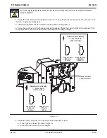
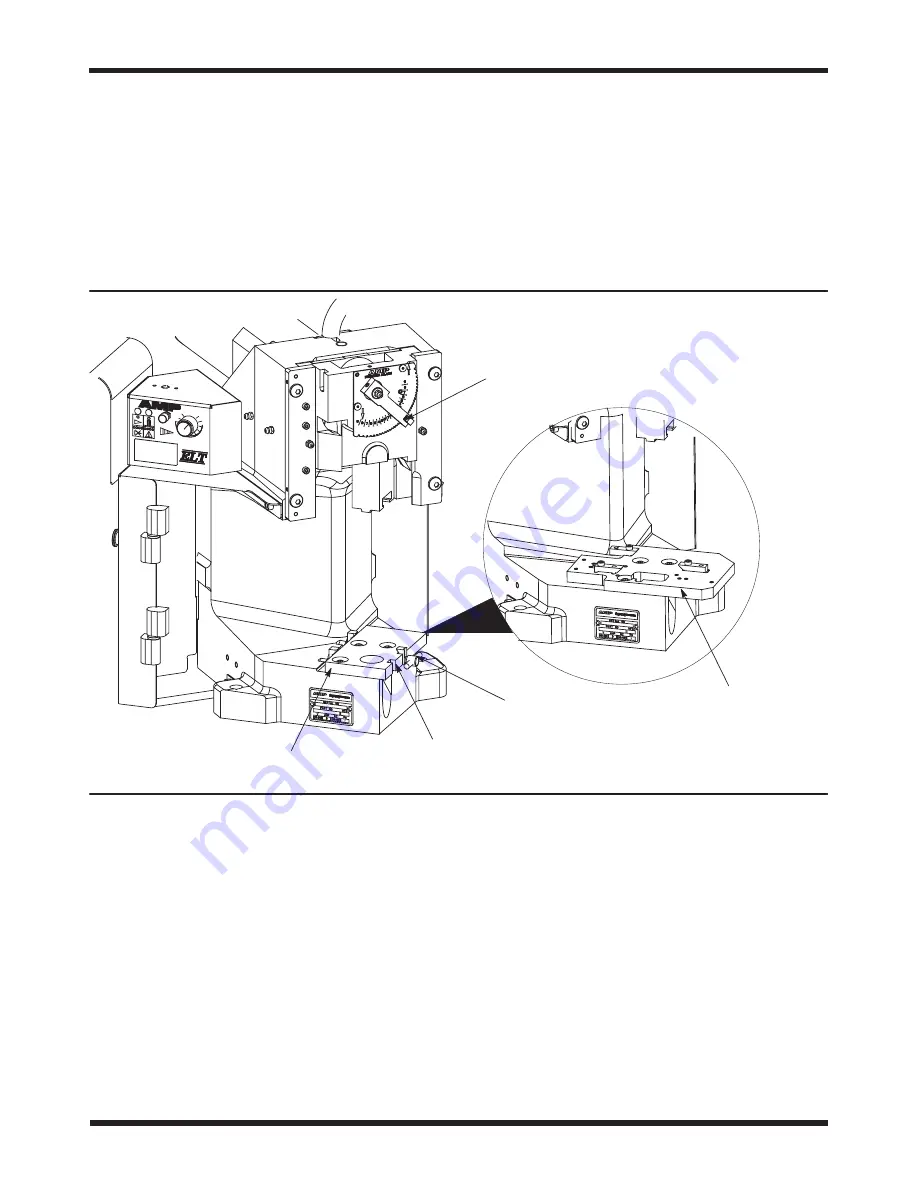
base plate provides the mounting surface on which the applicator is installed. The quick–release
latching feature on Machines –1, –2, –5, and –6 permits fast, easy installation and removal of the
applicator. Note that Machines –3 and –4, restricted to Asia/Pacific market, do not include the
quick–release latching feature. See Figure 5.
4. An
optional crimp height adjustment group uses an eccentric located in the ram linkage, along
with detented stops in the mechanism to adjust the crimp height. Indexing the mechanism in either
direction will change the crimp height in increments of approximately 0.013 mm [.0005 in.] per step.
Figure 5
Base Plate for Machines
-1, -2, -5, and -6
Quick-Release
T-Handle
Shown with Optional
Precision Crimp Height
Adjustment Mechanism
Base Plate for Machines
-3 and -4
Alternate Rear Stop
Mounting Position
2.2. Electrical Description
The ELT machine electrical components consist of the operator control panel, the motor, and the CPU/motor
controller package. The machine operates on 100/240 Vac, 50/60 Hz, single–phase current with ground. The
machine will automatically detect the supply voltage and adjust the controller accordingly.
The operator control panel (Figure 6) is mounted on the left side of the machine frame. The control panel
consists of two indicator lights, one jog button, and one speed control knob, with icons depicting each function.
See Paragraph 4.1 for control panel operation.


