


409-10016
ELT Machine 1338600-[
Rev H
34 of 34
Tyco Electronics Corporation
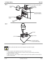
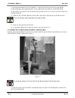
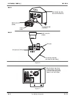
10. Turn the air “on” by moving the slide valve (Figure 29)
toward the filter.
The air can be turned off "by moving the slide valve away from the filter.
11. Lock the air in the “off” position. Turn the air “off” and clamp the valve lockout in position as shown in
Figure 28.
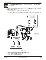
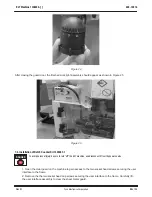
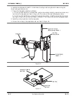
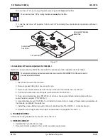
Figure 31
SocketHead
Cap Screw
Air Feed Clamp
Universal ELT Machine
Base Plate
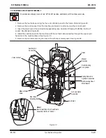
7.5. Installation of Precision Adjustment Kit 1424208-1
Refer to Customer Drawing 1424208, and install the optional precision adjustment kit as follows:
To avoid personal injury, electrical and pneumatic power must be DISCONNECTED at the source prior to
precision adjust kit installation.
1. Disconnect power to the machine.
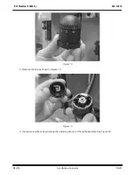
2. Remove grease fitting from non–eccentric pin.
3. Remove two double setscrews from the top of the ram that retains the eccentric pin.
4. Pull the non–eccentric pin and replace with Eccentric Pin 354510–1.
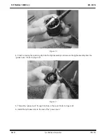
5. Drive two slotted spring pins (PN 21920–5) into ram housing and attach indexing plate with two
socket head cap screws (PN 992285–1).
6. Assemble Adjust Lever 1320363–1 and install onto eccentric pin. Apply a thread–locking substance to
the threads, and tighten the setscrew.
7. Install the grease fitting (removed in Step 2) onto Eccentric Pin 354510–1. Lubricate the pin.
8. Adjust the shut height and crimp height as described in Paragraphs 6.2 and 6.3.
8. TROUBLESHOOTING
Contact the Tooling Assistance Center at
1–800–722–1111.
9. REVISION SUMMARY
S
Updated the Tyco Electronics logo
S
Document format updated to the current corporate requirements
NOTE
i
DANGER


