Tyco Electronics 1338600 Series Скачать руководство пользователя страница 16

409-10016

ELT Machine 1338600-[

Rev H

16 of 34

Tyco Electronics Corporation

the position of the speed control knob. The new speed setting will remain active for a maximum of three
seconds after the Jog button is released, or until the crankshaft completes the cycle. If the cycle is not
complete and the Jog button is again pressed within three seconds from its release, the crankshaft will
rotate at the speed defined by the position of the speed control knob. Failure to push the Jog button within
the three seconds of its release will cause the crankshaft jog speed to revert back to the initial minimum
default value. After the Jog button is released, the speed control knob can be rotated in either direction to
increase or reduce the crankshaft jog speed, but Jog button must be activated again within three seconds
of the release or the speed will revert back to minimum default speed. The speed control knob can be
reset as many times as desired.

The machine will exit the Jog (With Guards Disabled) Mode whenever the guards are closed or the power
is turned “off.”

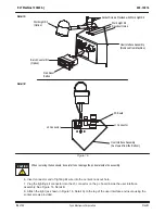
The speed control knob in Figure 10 also adjusts the air feed timing. Normally the air feed timing is set at 280 ms.

When the speed control is set at less than 50% of its maximum setting (pointing straight down or counterclockwise

from pointing straight down), the air feed timing changes to 440 ms. This is done to accommodate applicators that

have longer than normal air cylinders.

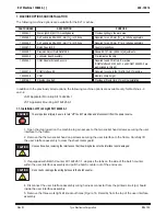
The green flashing status indicator flashes a specific number of times to represent a corresponding fault. For
example, the green status indicator will flash two times (each followed by a one second pause) to indicate that
the machine guard opened while the machine was running. Refer to Figure 11.

FAULT INDICATOR CODE

(Number of Consecutive Flashes)

ELT MACHINE FAULT

2

Theguard opened whilethemotor was running.

3

The guard must be closed before proceeding.

4

Motion from top dead center (TDC) was not detected.

5

The TDC switch was not sensed.

6

A bad PWM IGBT was detected.

7

A bad Jog push button input was detected.

8

A bad footswitch input was detected.

9

A bad DC bus relay was detected.

10

A bad jog enable input was detected.

11

Thelinevoltageis not within specifications.

12

A bad spare input was detected.

 Figure 11

4.5. Crimp Height Adjustment

On ELT machines that do not include the precision adjustment feature, the crimp height must be adjusted at
the applicator. Refer to the instructions provided with the applicator to perform this adjustment. Refer to
Paragraph 6.3 for procedures to adjust the crimp height using the ELT machine precision adjustment feature.

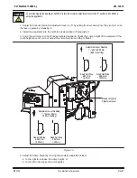
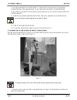
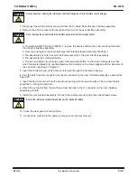
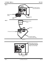
4.6. End-Feed/Side-Feed Applicator Conversion

When changing from an end–feed applicator to a side–feed applicator (or from a side–feed applicator to an
end–feed applicator), the reel support assembly must be moved to the opposite side of the machine. With the
terminal reel removed, lift and rotate the reel support bar to the opposite side of the machine. Mount the
terminal reel on the reel support and load the terminal strip into the applicator. Remove the metal terminal
lead–in and thumbscrews and move to the opposite side of the machine. Move the machine lubricator bowl to
the opposite side of the machine as required.

Lubricator Bowl Assembly 354550-1 is an optional accessory.

NOTE

i

NOTE

i

Содержание 1338600 Series

Страница 1: ...tion 9 3 2 Installation 9 3 3 Considerations Affecting the Placement of Bench Machines 10 4 OPERATION 11 4 1 Control Panel Operation 11 4 2 Applicator Installation 11 4 3 Setup 14 4 4 Mode Selection a...

Страница 2: ...e application equipment D NEVER insert hands into installed application equipment D NEVER alter modify or misuse the application equipment TOOLING ASSISTANCE CENTER CALL TOLL FREE 1 800 722 1111 CONTI...

Страница 3: ...onitor CQM Sensors 1725950 7 1338600 8 ELT Machine with 30 mm 1 1 8 in Stroke Tool less Precision Crimp Adjust CQM Sensors 1725950 8 1338600 9 ELT Machine with 40 mm 1 5 8 in Stroke Tool less Precisio...

Страница 4: ...in moderate or severe injury Denotes a condition which may result in product or equipment damage Highlights special or important information Reasons for reissue are in Section 9 REVISION SUMMARY 2 DE...

Страница 5: ...ng Machine Post Feed 690501 4 1 5 8 in Stroke Applicator for Model T and Model G Terminating Pre Feed 690602 5 Model T and Model G Terminating Machines Post Feed 690501 3 Heavy Duty Industrial HD I Ap...

Страница 6: ...ndexing the mechanism in either direction will change the crimp height in increments of approximately 0 013 mm 0005 in per step Figure 5 Base Plate for Machines 1 2 5 and 6 Quick Release T Handle Show...

Страница 7: ...f the electronics necessary to operate the machine See Figure 7 The CPU motor controller package contains high voltages which can remain even after power has been removed Contact the Tooling Assistanc...

Страница 8: ...Machine 1338600 Rev H 8 of 34 Tyco Electronics Corporation Figure 7 DC Motor Back Cover CPU Motor Controller Behind Back Cover Motor Access Cover Reel Support Hole Power Switch Circuit Breaker Termina...

Страница 9: ...ne 4 Hole for Customer Supplied Lift Ring Quick Release T Handle for Machines 1 2 5 and 6 Shown with Optional Precision Crimp Height Adjustment Mechanism 3 RECEIVING INSPECTION AND INSTALLATION 3 1 Re...

Страница 10: ...ved if 1 the bench is of appropriate height preferably with sound deadening rubber mounts 2 the machine is properly located on the bench with ample work areas on both sides to facilitate work flow 3 t...

Страница 11: ...n may require a wedge shaped block placed under it E Scrap Removal A suggested method of scrap removal place a tray on the right side of the machine under the cast slot in the frame to capture the scr...

Страница 12: ...and insulation crimp discs so that the letters and numbers on the applicator pad align with the front pad on the ram post adapter 5 If the applicator is an air feed type connect the airlines to the v...

Страница 13: ...he green indicator stops flashing The yellow indicator on the top of the control panel indicates the guard status Note that this indicator is not active on Machine 4 When the yellow indicator is on an...

Страница 14: ...t complete the cycle either adjust the speed control knob as described below or complete the cycle using the footswitch at a speed determined by the speed control knob after the Jog button has been pr...

Страница 15: ...or open To activate this mode turn off power and open the guard door Turn the power back on and immediately after the machine ready and guard disable indicators flash on press and hold the Jog button...

Страница 16: ...indicator will flash two times each followed by a one second pause to indicate that the machine guard opened while the machine was running Refer to Figure 11 FAULT INDICATOR CODE Number of Consecutive...

Страница 17: ...ards with a clean soft cloth DO NOT USE ANY SOLVENT TO CLEAN THE GUARDS Solvent could damage the guards 5 2 Lubrication The moving parts of the machine require regular lubrication to ensure reliable s...

Страница 18: ...shut height refer to 408 8535 for instructions on use of the gage 1 If installed adjust the manual precision adjustment lever to the 0 setting 2 Remove the access cover Figure 7 on the end of the moto...

Страница 19: ...am post adaptor and shims Change the shim thickness as required to adjust the shut height Shims contain 051 mm 002 in peel type laminations b Re install the ram post adaptor Insert both screws in the...

Страница 20: ...to crimp three sample terminations Check the crimp height of the samples If the crimp heights are not correct adjust the crimp height according to Step 4 Figure 14 Adjustment Lever Reading above 0 00...

Страница 21: ...ot cannot be secured in place A Standard Guard Insert 1 679532 0 1 Slide the insert into the rear slot of the guard door Secure the insert to the door with two screws placed through the large square h...

Страница 22: ...ard Insert A B GUARD INSERT DIMENSION PART NUMBER DESCRIPTION A B 354529 2 Standard Away from the Applicator 7 80 307 6 35 250 1 679532 0 Standard Close to the Applicator Shipped with the Machine 6 22...

Страница 23: ...addition to the previously listed options the following machine options are available only for Machines 3 and 4 JAM Applicator Mounting Kit 1424268 1 JST Applicator Mounting Kit 1424269 1 7 1 Install...

Страница 24: ...e Assembly As Viewed from the Bottom PC Board J1 Connector J3 Connector When removing the knockouts be careful to not damage the pc board inside the assembly 6 Insert connector end of lighting kit wir...

Страница 25: ...et head screws Be sure the interface assembly wiring harness is not pinched or kinked 12 Close the clear guard on the machine 13 Connect the machine to the power source and turn the machine on 7 2 Ins...

Страница 26: ...Machine 1338600 Rev H 26 of 34 Tyco Electronics Corporation Figure 18 2 Remove the cap as shown in Figure 19 Figure 19 3 Using a screwdriver begin prying the retaining clip out of the light assembly...

Страница 27: ...ure 20 4 Finish removing the retaining clip from the light assembly and remove the light assembly from the goose neck Refer to Figure 21 Figure 21 5 Thread the goose neck through the hole in the cover...

Страница 28: ...orporation Figure 22 7 Install the retaining clip in the light assembly Refer to Figure 23 Figure 23 8 Replace the cap on the light assembly and align the marks as shown in Figure 24 Turn the cap cloc...

Страница 29: ...ch Counter Kit 1424267 1 To avoid personal injury be sure to turn off the ELT machine and disconnect it from the power source 1 Open the clear guard on the machine to gain access to the two socket hea...

Страница 30: ...ighten the locking screw of the larger dial button on the shaft of the switch so that when the dial is rotated fully counterclockwise the indicator on the dial is aligned with the indicator on the sil...

Страница 31: ...ckout for Batch Counter Kit Batch Counter Kit Option Detail A Detail B PC Board J2 Connector on PC Board User Interface Assembly As Viewed from the Bottom Red Reset Button Batch Counter Kit Option Fig...

Страница 32: ...cable assembly see Customer Drawing 1424266 into the J7 socket See Detail in Figure 28 4 Install the control panel into the machine with the air feed cable assembly through the upper right hand slot i...

Страница 33: ...wn in Figure 30 Then remove the back left baseplate clamp b For Air Feed Kit 1424266 2 universal ELT machine base plate install the socket head cap screw as shown in Figure 31 and Air Feed Clamp 13389...

Страница 34: ...llation 1 Disconnect power to the machine 2 Remove grease fitting from non eccentric pin 3 Remove two double setscrews from the top of the ram that retains the eccentric pin 4 Pull the non eccentric p...

Отзывы: