37
7200790 Service Manual for the HELION
®
XENION
®
Surgical Lighting System GB
12 Testing the Electrics of the HELION M+ / L+ Lamp
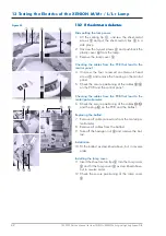
Figure 02
12.2
12.2
12.2
12.2
12.2 TTTTTesting the operating voltages, fuse
esting the operating voltages, fuse
esting the operating voltages, fuse
esting the operating voltages, fuse
esting the operating voltages, fuse
and cables in the lamp
and cables in the lamp
and cables in the lamp
and cables in the lamp
and cables in the lamp
The test is described using the HELION L+ as an ex-
ample.
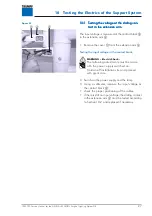
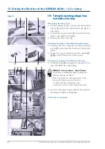
Dismantling the lamp cover:
1. Lift the sealing lip
1
, unscrew the sheet-metal
screws
2
and put the sheet-metal clips
5
in a
safe place.
2. Unscrew the two set screws
4
and push back the
plastic cover
6
from the lamp.
3. Remove the lamp cover
3
.
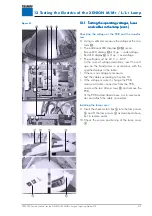
Check the cables on the PCB and control panel:
4. Unscrew the four recessed countersunk head
screws
7
and remove the housing on the control
panel.
5. Check the secure positioning of the cables
8
/
C
/
D
on the PCB and the control panel.
Checking the fuse and the voltage at the PCB:
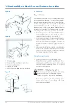
6. Check the fuse
A
and replace if necessary.
Fuse type: T1L 250 V (1 A slow-blow)
WARNING – Electric Shock:
The following measurements must be made
with the power supply switched on.
Cordon off installation site and proceed
with great care.
7. Switch on the power supply and the lamp and set
the lamp to maximum brightness.
8. Using a voltmeter, measure the voltage at the ter-
minal strip
9
:
• The voltage must be between 23 V and 30 V DC.
-
In the case of voltage deviations, reset the volt-
age on the transformer in accordance with the
specified values in the table.
• If there is no voltage to measure:
-
Test the cables according to Section 10.
• If the voltage is correct, change the PCB:
-
remove all cable connectors from the PCB,
-
unscrew the two Allen screws
B
and remove the
PCB,
-
fit the PCB as described above, but in reverse or-
der, and attach the cable connector.
Continued on next page.

